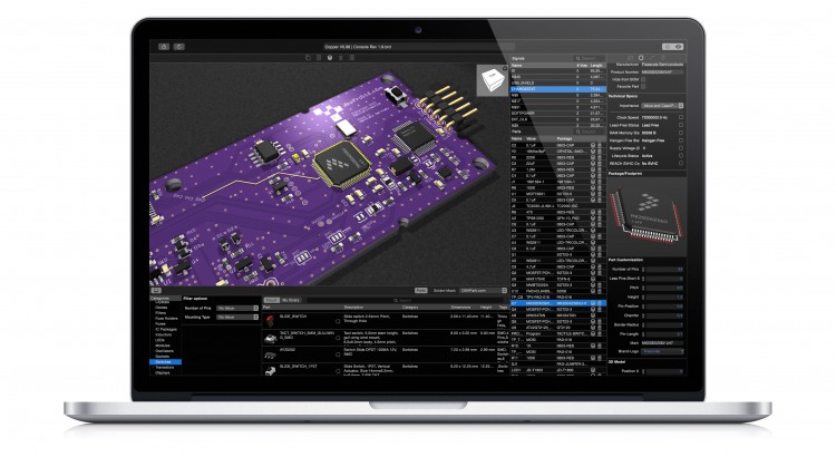
Copper is a Mac application that is able to open EAGLE files and visualizes and analyzes your PCBs. Copper also generates 3D models of your PCBs and renders them to photo realistic images. Copper also helps in building BOMs by directly implementing Octopart.
Printrbot Simple 2016 – Hardware (PCB) explained
This blog post describes the details about the hardware, more specifically the PCB that I have developed for the display component of the new Printrbot Simple 2016. As we believe in Open Source we have published everything under the MIT license. Have a look at the code respository, too.
To give you some context why we have chosen these components please first read my Behind the Scenes report that describes the process of selecting the right components for our purpose.
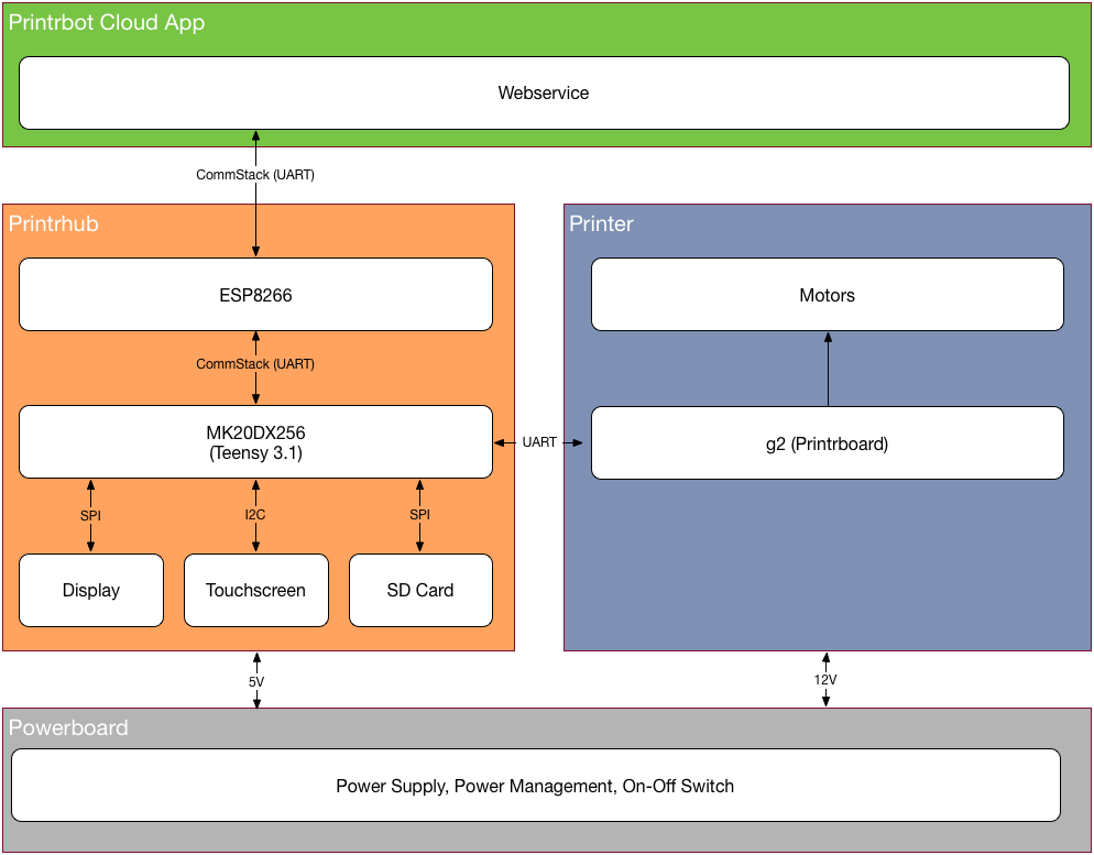
Block diagram
Let’s have a look at the Block Diagram of the Simple 2016 and how various components are connected. First we have a very clever power management that delivers enough current for all the motors and PCBs but also does that secure and with great efficiency. Next there is the Printrhub, which is the display component of the printer. The hub also controls the Printrboard and the ESP module to communicate with the Printrbot cloud that holds all the projects, materials and settings of the user. Last but not least there is the printer itself, powered by the g2 Printrboard with advanced motor handling features and advanced algorithms for great prints.
Printrbot Simple 2016 CommStack explained
This is series 3 of the Printrbot Simple Behind the Scenes report. In this post I will go into detail what CommStack is and why we developed it. As you know Printrhub has two MCUs: ESP8266 and Teensy 3.1. There are more details on the hardware design here, but to make it short hier is a block diagram of the setup to get us started:
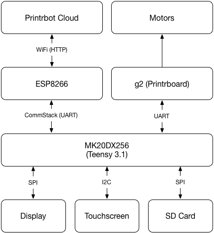
As you can see, MK20DX256 (our main processor) has quite a lot to do. And if you have read the document describing the display system you know, that we cannot block the main loop any time. Because that would mean that the display is unresponsive or worst, the printer does not get new commands and stops the print.
Let’s think about a usage scenario and translate that to tasks of work being done by this system: Starting a print.
If you start a print, you select the print job on the display. MK20 will ask for touches in its main loop and reflects those interactions on the screen. When you press the PRINT button, MK20 checks SD card to see if that file is already downloaded (available on the SD card). If it’s not, MK20 has to ask ESP to download the file. ESP downloads the file and sends the data to MK20 which in turn writes the data to the SD card.
Remember, we don’t want to block the main loop. We need to do that in an asynchronous way. What I mean with that is that we must split that into very small pieces and execute them one after the other in the main loop, but in between we give control back to other parts of the system.
Printrbot Simple 2016 Display System explained
Over the past few months I have developed the LCD component of the new Printrbot Simple 2016. In this post I want to explain how the display system works. It makes sense you read the Behind the Scenes report of building the Simple 2016 first, as that gives you some context to what I am talking about here.
Early on we decided to use a display with the ILI9341 display driver chip as there is a very fast display driver available. We also decided to use the 2.8 inch display as this had the best fit in the new Simple model. We also decided to use the FT6206 touch screen although this can be easily exchanged as most touch screens are connected via I2C and the protocol is very simple to implement.
Adafruit has exactly this display as a break out board available. PJRC also sells the same display, but with a different touch controller. However, it’s not an issue to adept our code to another touch controller. And, of course there are display modules available at eBay. Just make sure your display has the ILI9341 display driver chip installed. Although our display system is very flexible you get best results if you choose a 320×240 pixel display to get quick results.
How displays work
Displays have a memory area and small pixels are connected to this memory (not in a circuit kind of way but you get the idea). When you change the bytes in that memory area the display reflects that. You modify this memory area using SPI to write data in specific memory regions. That takes time. And as the display immediately reflects any changes you can see the display building up the final user interface. Worst, you cannot just first fill a rectangle and then draw some text on it, as it would result in flickering. Animation is practically impossible although Paul did a very good job of making it as fast as possible.
There is a very easy way of fixing that: a back buffer. You store a memory area in your MCU that mimics that memory area of the display. You make changes there, you can overwrite data multiple times. And when everything is composed you send the whole area to the display. This does not allow for fast animations, too. But you get a nice, polished look and feel. But, Teensy does not have enough memory to store a back buffer!
Behind the Scenes: Printrbot Simple 2016
If you know my blog, or by just having a look in the archive you will quickly find out that I am a fan of printrbot. My very first 3D printer has been a Simple Metal. This has been a great starting point into 3D printing. But it had its caveat that forced me to write down a blog post on how to fix the little issues that I had when I first got that printer. But I loved it for its simple yet effective design and it’s gorgeous print quality.
Last year in November I released my Mac Application Copper (http://www.copper-app.com). It’s a companion application for Eagle CAD that fills the gaps where Eagle fails. I tried to advertise it
using typical methods like buying Ads at Facebook and Twitter. That did not really work as this product is a niche product which is hard to market in these channels. I had a lot of costly clicks from Windows users that were interested if this application is available for Windows, too. It’s not! So I had to find different ways of getting some traffic on Copper.
I looked around in my office and found my Little Helper (http://www.appfruits.com/2015/12/little- helper/). It’s one of my earlier electronics project that is a great helper in my lab. I always thought about doing a Kickstarter for it, but did not as baking so many projects at Kickstarter I knew: It’s hard to get a polished project in time. So I decided to release it to the public under open source. I got quite a lot of traffic on this and Copper sales increased dramatically. By giving something back to the community that helped me to learn electronics faster than I thought I got a lot of traffic and free advertisement for my products and webpage. If you consider doing the same: Do it! You will likely gain more than with a failed Kickstarter!
Product Development done right
You may ask: What the hell is the point here? So, let’s get started: The other day I noticed in a Copper sales report that someone with a @printrbot.com email address bought Copper. Being a fan of them I sent them an email thanking them for purchasing Copper and telling them I loved their Simple Metal. This changed everything! We got in contact and Mick told me he learned about Copper by reading my blog post about Little Helper (http://www.appfruits.com/2015/12/little- helper/), which he noticed in a blog post on hackaday.com (http://hackaday.com/2015/12/25/little- helper-open-source-hardware-hacker-multitool/). He also told me he uses Copper to quickly checkout pin numbers and signals when working on the firmware for their printers.
A few days later I had a Skype chat together with Mick and Brook Drumm (founder and CEO of printrbot) and they asked me if it would be possible to use Little Helper as a display and input system for their printers. A year ago most 3D printers used a tiny LCD screen with a rotating input wheel (rotary encoder) and a SD card slot for printer control. Little Helper seemed like a good fit and a step forward.
So, after one Skype chat we started the project to create a LCD display for the next generation of printrbot products. This is awesome. I don’t think a lot of CEOs in Germany would start things like that. This is visionary and full of risks. They are in the US, I am in Germany. We have a time difference of 8-9 hours. There are so many things that could go wrong. In Germany you would rather want to hire someone around you. You want to be able to control what he/she is doing. Brook just has been confident that it will work out. I am running a German internet company full time (4players.de (http://www.4players.de)). These projects and Copper are filling my spare time that I need to fill with creativity and product development to be healthy and happy ;-). This has been a great chance for me to do something with a little more impact than working in my lab for myself or the open source community.
Finding the right shape
After our Skype call I had written down a document describing the details of Little Helper and some issues with that design that came to my mind and a few alternatives. This is what German people do, they structure stuff ;-). While I was structuring stuff, Brook and Mick thought about the product as a whole. After some more eMail discussions the final product quickly got a rough shape. This is a quote from of one of our first discussions:
Anyway, if we all agree a touchscreen + teensy is a viable path, let’s set that in stone. I realize it won’t leverage much of the little helper, but I want to make the right decision and it seems it will reduce cost, complexity and future proof the UI
Does it make any sense to put the esp and Sd card on the same board?
If you want to run a business or want to succeed in product development you just learned what is essential: Have the courage to decide on things. We discussed a few days and already had a clear roadmap what we wanted to develop. Today there are more options than you can count, for each and every component on the board. Of course we had a look at other things, too. For example we looked at Photons for WiFi connection but due to some restrictions in their business model and some technical aspects kept us sticking with the good old ESP8266.
You may ask why we opted for two MCUs on one board, the ESP could have run the display, too. Why adding the Teensy? Well, I knew from some tests before that Paul (Teensy developer) created a very, very fast display driver for ILI9341 based displays that has been way faster than any other MCU. And the overall support for high quality code and drivers for Teensy promised fast development opportunities. Talking to the web is an asynchronous task, while handling
touches, running a display and controlling a printer is a synchronous task. I think it’s been the right decision to let ESP talk to the web, while Teensy handles the rest.
This is the final specification that we had set in stone before I even launched EAGLE or my development IDE:
- Teensy MCU (3.1)
- ESP8266
- ILI9341 based 2.8 inch display microSD card slot
- Capacitive touch
To give you an idea of the time frame: I had the first contact with Mick on January 5th, and we decided creating it with the final specifications on January 11th! Deciding early and sticking to that makes it way easier for larger teams to work on the same product. If you always change specifications and details you always reset your team. That kills motivation. Not in this project. I don’t think I ever slept less than during the last few months, but it’s been such a great adventure and journey!
Technology described
Arduino and Teensy made it so much easier to create products like this, but it’s still a lot of work, especially if you want to build professional products. People are used to a very high standard for touch screen based displays. They want animation, fast refresh rates and a very responsive experience. The software that is needed to run a user interface on such a limited device has not been available and so we had to develop it. Communicating with the ESP8266 module is easy, just use UART connection available on nearly every MCU. But it’s not easy if your host MCU has to get other things done while ESP8266 is downloading content. As you can see we had to develop a lot of software.
In our very first call Brook made clear that he wanted to Open Source everything that we would develop. The good news for you: We made that true today. You can have a look in every detail of our display system and core technology. In the next serious of documents I will try to explain how everything works together and in detail.
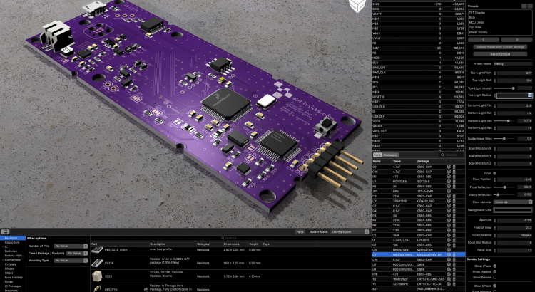
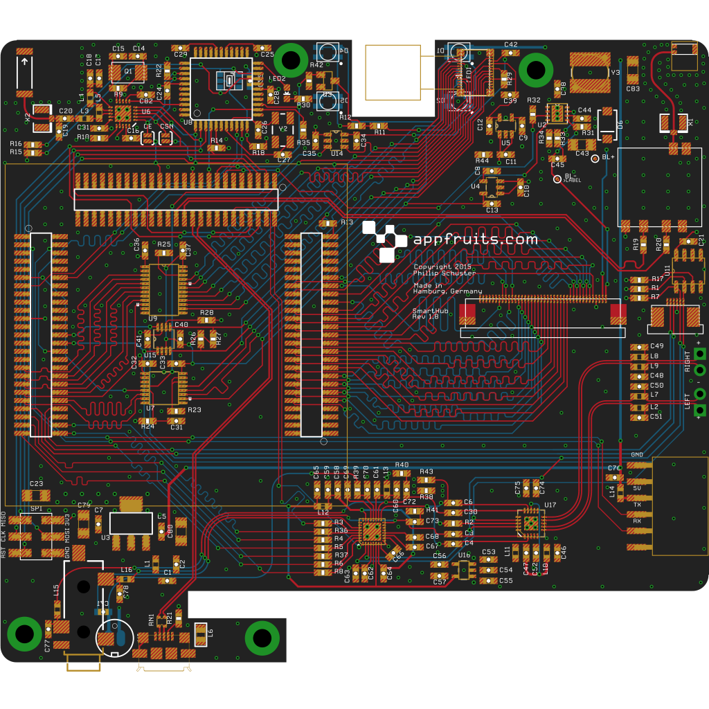
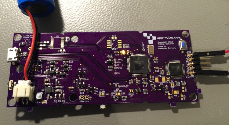
Hardware and PCB
Compared to the time spent on software development, hardware development was peanuts. The first PCB I developed worked great and we had a good development platform to work on software. Overall we had four revisions of the hardware.
Read more about the process of getting the final hardware for the display and learn why about the details of the PCB and how you can make use of it in your own projects.
Display system
The Display system (http://www.appfruits.com/2016/11/printrbot-simple-2016-display-system- explained/) built upon the amazing and very fast display driver developed by Paul J. Stoffregen (Teensy creator). Although it uses SPI (which is not the fastest method to connect to a display) it’s very fast and just works great. We have written our own driver for the FT6206 touch controller we use, although it’s been heavily influenced by the driver from Adafruit.
Displays have a memory area and small pixels are connected to this memory (not in a circuit kind of way but you get the idea). When you change the bytes in that memory area the display reflects that. You modify this memory area using SPI to write data in specific memory regions. That takes time. And as the display immediately reflects any changes you can see the display building up the final user interface. Worst, you cannot just first fill a rectangle and then draw some text on it, as it would result in flickering. Animation is practically impossible although Paul did a very good job of making it as fast as possible.
There is a very easy way of fixing that: a back buffer. You store a memory area in your MCU that mimics that memory area of the display. You make changes there, you can overwrite data multiple times. And when everything is composed you send the whole area to the display. This does not allow for fast animations, too. But you get a nice, polished look and feel. But, Teensy does not have enough memory to store a back buffer!
We had to develop a whole new way of handling the pixels of a small display. And we managed to do that. Our display system is versatile, fast, easy to use and very flexible. It permits very large scrollable areas without eating a lot of memory and while keeping very fast refresh rates and responsiveness. It’s an amazing system and you should learn how it works (http://www.appfruits.com/2016/11/printrbot-simple-2016-display-system-explained/) and how you can use it yourself in your next project.
CommStack
Another system we have built from scratch is CommStack. It’s a request/response based asynchronous non-blocking full duplex communication system based on UART. It is the robust communication stack permitting the main MCU (Teensy) talking to ESP8266 without getting blocked or loosing data while doing other things. It also allows ESP to talk to the Teensy at the same time.
This is another amazing technology that we built and that made our lives so much easier. Once we had CommStack up and running it’s been very easy to implement new features as we just could use the MCU that is best used for the case and use CommStack to coordinate task management.
Read more in our CommStack documentation to learn how it works and how you can use it yourself.
Over the air firmware updates and flashing Teensy
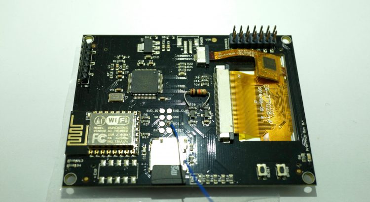
This is huge: When we decided to use two MCUs on one board (ESP8266 and MK20DX256LHV7) we also needed a way to flash firmware on them. On a dev board it’s easy. We added a FTDI header for flashing ESP8266 and we added the amazing PJRC Teensy bootloader chip that permitted us to flash Teensy firmware using USB. But in the final system we wanted over the air updates. We wanted a printer that does not need to be connected to a PC/Mac. And we want to be able to add features to the printer, which only makes sense if customers can update the firmware easily.
As Teensy does not support over the air updates, we had to develop it ourselves. Read on and learn how you can add over the air updates to your own Teensy based projects by just adding a ESP8266 module!
Final words
Looking back I think it has been very important to write down the components we wanted to use and to stick with them. Every core technology described above had its hard days. Days where we have been frustrated and didn’t make any progress. Those days are very hard. And if your company culture is to find ways around issues than solving them (I think there are quite a lot of companies working like that) you never get finished with things. We could have exchanged the Teensy MCU with a more powerful one with more RAM, with more pins to connect the display via parallel (faster) connection we could have worked around that. But perhaps we had a hard time to get over the air updates up and running with this new MCU. Who knows.
I think it’s our job as a product developer to solve these issues and so did the whole team. The whole team forced me and motivated me to solve these issues. And we were so excited when things finally worked. That is what you need: Backup for hard times and party when it finally works :-).
Time difference has been good and bad at the same time. Due to 8-9 hours time difference we only had a short window for chatting each day. It forced us to organize our work but modern tools like Github and Skype allowed us to do that very easily. For me time difference has been great as this project never collided with my full time job. While I have been working my daily job the printrbot guys have been sleeping, and once they started their day I already had finished my daily job and were able to work on this project. Time difference had been an issue in the last weeks of polishing the product. It required us to package all that little pieces we developed in the past months and it’s been frustrating as the team testing the printers sometimes had to wait a day until I have been able to fix the issue.
If you ever have the chance to work with Printrbot: Do it! You will not regret it. You will learn a ton, you will have a lot of fun and you will have new friends after that. This sounds like a final conclusion, but think about that like a season 1 final: We just got started!
Xcode quick tip: Copy failed during export or uploading to App Store
I have been working quite some time on version 1.3 of Copper, our Mac EDA application. Check it out if you didn’t know yet. This version brings the ability to import your own STEP models of parts to create wonderful 3D models of your PCB. And this feature also added a lot of (partly external) code to my project.
After archiving the project I wanted to upload it to the App Store. So I went in the Organizer of Xcode, selected the newly created archive and clicked on “Upload to App Store”. But, export failed. I got a strange “Copy failed” error with a hint to some logs. Reading these logs is hard. As I added various Frameworks and external libraries to my application I thought it must have been something to do with that. So, for many months I tried again and again, I ripped my project apart but I never really got this issue solved.
Looking at the logs I noticed that it points out:
...
2016-11-16 09:53:45 +0000 652253 bytes for ./Contents/Resources/woodTexture2.jpg
2016-11-16 09:53:45 +0000 /usr/bin/ditto exited with 1
2016-11-16 09:53:46 +0000 [MT] Canceled distribution assistant
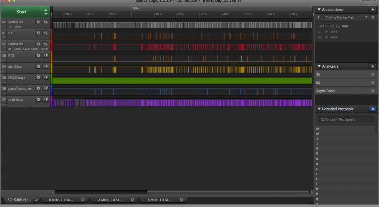
Do I need a Logic Analyzer?
In one of my previous posts I tried to answer the question: “Do I need an Oscilloscope?“. The answer has been a short: Yes, under some circumstances.
But, there is another great measurement tool available: A Logic Analyzer. There are a lot of options, and a quick look at them reveals one thing: They are so much cheaper than oscilloscopes with the same amount of channels. The cheapest oscilloscope from Rigol, the 1054Z with 4 channels costs about $399 (but more if you add some options), the cheapest Logic Analyzer from Saleae costs $109. If you are interested in buying an oscilloscope, but don’t want to spend so much money at it (yet), is a Logic Analyzer an alternative?
Well, the good news is yes! Under some circumstances. Sometimes it’s even a better buy than an oscilloscope. Let me first explain what a Logic Analyzer does and why it’s so useful and often more useful than an oscilloscope.
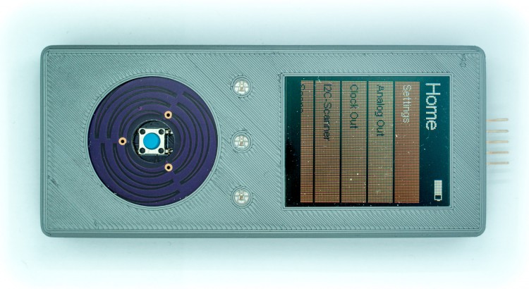
Little Helper
If you have read one of my previous blog posts about building a custom Teensy you already know I have been working on a device based on the Teensy design.
Working in my lab with electronics I came across different little challenges once in a while, and noticed that I am missing tools to handle them efficiently. Just a quick list, I am sure you could add various items to the list:
- What is the I2C address of a chip? (yeah, you can work through the Datasheet but the Datasheets I know don’t have an outline topic for this. It’s somewhere hidden deep in text somewhere)
- What is the voltage range of the analog sensor in my current environment (take a photo sensor)?
- Generating PWM or DAC signals
- Does this circuit do anything?
- Does this circuit do anything specific?
- Reading serial output of your Microcontroller/Arduino project
Of course these aren’t any issues that you could not handle with the tools you have. But each of these take time. Checking an IC for it’s I2C address is easy: Connect it to your Arduino Uno, firing up the I2C Scanner sketch and you are good to go. That is 10 minutes minimum finding your Uno, wiring it up, firing Arduino IDE, uploading the sketch. And everything while your workspace is full of components, wires and stuff for the actual project you are working on.
I had been working on wireless sensors for a while that should take the least amount of power possible. You cannot add status LEDs as they draw way too much power. I had those PCBs lying around and had no clue if they do anything. I had to carry my laptop around, connecting it to the PCB to read the serial port to see what it does.
Why, the heck did I learn all that programming and electronics stuff and not using it to solve that issue. I thought of a small, portable device featuring some ports to connect stuff like sensors and other circuits and some menu driven user interface to trigger various modules doing tests, reading data, you get it.
Announcing Copper Beta
It all started with quite a complex PCB that I have been developing with Eagle CAD. A 4-Layer PCB with a lot of parts (>100) and quite a few ICs with a lot of pins. All these traces, all this pins and pads. There are so many possibilities to screw it up, that I always thought about this sentence all of you interested in this kind of stuff know well: “Hardware is hard”. It is.
And after triple checking every pin and trace, working through dozens of data sheets and controlling pin layouts I had it in front of me: My very own awesome PCB and hundreds of parts lying in front of me. I have a reflow oven and had to place parts on the board, prepared with solder paste. As you perhaps know, solder paste dries out after some time, so I had to be quick. I knew, that I had to place the 0.1uF capacitor on C1,C2,C3,C5,C6,… Searching for these parts on the boards silk screen drove me crazy. I had printed out assembly plans, etc. I had my MacBook running Eagle and started to search for each Part to get it selected in the board to know where to place it.
In these hours the idea of Copper took shape. At first, I only wanted a software that renders a simple representation of the PCB with a parts list. Select one or multiple parts and they are highlighted on the board. I fired up Xcode and a few days later I had it up and running. And it worked great. Whenever I discovered issues and shortcomings in Eagle CAD or my workflows and didn’t find a solution I added my own solution to “EagleCAD Viewer” (that’s been the name for quite some time).
Although I just did write this application for my own use, I invested quite some time to get rendering right, make the App look great and ironed out any bug I could find. Why? Because I just hate buggy, bad looking software, especially when it’s my own software.
A few months ago I decided to commercialize my Application and named it Copper. I think you will love it, and I really hope it will make your life easier. But before I sell this Application I must be sure it works great on all Mac OS X versions and with your PCBs. I don’t want you to buy into a beta test.
Update: Copper is available now for purchase (24,99 USD/Euro). There also is a free, fully functional Trial for Mac OS X 10.10+ available.
More Info and the Trial is available at our Copper product page.
Please report any questions to: support@copper-app.com.
Building your own custom Teensy
UPDATE (November 24, 2016):
While this blog post still is very popular, it’s a bit old now. It still uses the old Teensy bootloader chip that is meanwhile deprecated and is not available anymore in larger quantities. However, I have been part of the dev team of the new Printrbot Simple 2016 and I have developed the display component which also uses the Teensy. Printrbot made everything open source.
If you are interested in building your own Teensy hardware, have a look in my Behind the scenes report and the Hardware explained report which makes the schematics and PCB available for download. This new PCB features the latest Teensy bootloader chip.
Although the bootloader chip is old that is described here, everything else like routing USB traces is not! Have fun reading it and let me know what you think!
UPDATE (December 15, 2015):
As you are reading this you might be interested in my custom built Teensy project named Little Helper. I made it Open Source under the MIT license including Schematics, Layout, BOM, 3D models of enclosing, and the complete Source Code. Have a look: Appfruits LittleHelper.
UPDATE (June 26, 2015):
Due to popular demand I have created a “reference board layout” and the schematics in EAGLE CAD (7.2) format. I created it by removing all components that were specific to my project. I just left in the Teensy part, the USB-port and a 3.3V regulator and rearranged the components so they fit in a small footprint. I have never produced the board but it should work (also it doesn’t do anything useful) as the components and layout have been working flawlessly in my own application.
This should speed up your development time for your own project. The board layout contains a switching regulator for the 3.3V which might be overkill if you are running your board of an USB-port as the provided regulator is mainly used with LIPO battery based projects and is hard to hand solder (I use a reflow oven which works quite well with QFNs). Use a simple LDO if you are just running your board with USB power. I have left the board layout for the switching regulator as it has been quite hard to get a good board layout with nearly no noise (switching regulators tend to be very noisy due to it’s nature) and should get you up and running quickly if you intent to do a LIPO-based project (of course you will need to add a LIPO charging circuit which can be found for example in Sparkfuns Power Cell product (see board and schematics for details).
All parts have an attribute named MPN for Manufacturer Part Number and MF for manufacturer. This way you can just use EAGLEs BOM-ULP script to export a BOM that you can directly upload to Mouser of DigiKey to get your parts.
Please note: Don’t order the MINI54TAN at DigiKey or Mouser. You will need to order the MINI54TAN at PJRC.com as this IC contains the core Teensy functionality!
You can find the EAGLE board layout and schematics in our Github repository: Custom Teensy 3.1 board layout and schematics. Please make sure to read this blog post before using parts or the whole “reference board” in your own project as there are quite a few things to consider which is largely documented and described below.
If you are reading my blog you might know that I really love Teensy. Teensy is an ARM powered very little Arduino compatible development board. It does one thing so damn good and I think that is very important for a development board and one of the keys to the success of Arduino: Easy programming. You do not need to connect wires and fancy boxes (JTAG programmers), just connect with USB and click on the program button.
But I am not a big fan of using development boards within final products. Although Teensy is really small it’s too high to pack two PCBs together. Using headers for easier soldering and it gets worse. If you really want to build small products you will often have to build your own PCB. Paul Stoffregen, the creator of Teensy enables these efforts by providing the bootloader MCU in his own store. They are very professionell. I had a few issues with german customs and they immediately sent out new ones and I received a refund for the first package that did not make it through.
Of course it’s not Pauls business model to help you out building your own Teensy, although he was very helpful in the forum. You will have to rely on the great Teensy community or blog posts like this one.
As I had a bit of trouble to get my custom Teensy board up and running I will try to give you some advice on how to build your own. (more…)


