This is series 3 of the Printrbot Simple Behind the Scenes report. In this post I will go into detail what CommStack is and why we developed it. As you know Printrhub has two MCUs: ESP8266 and Teensy 3.1. There are more details on the hardware design here, but to make it short hier is a block diagram of the setup to get us started:
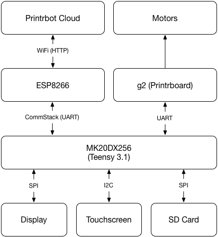
As you can see, MK20DX256 (our main processor) has quite a lot to do. And if you have read the document describing the display system you know, that we cannot block the main loop any time. Because that would mean that the display is unresponsive or worst, the printer does not get new commands and stops the print.
Let’s think about a usage scenario and translate that to tasks of work being done by this system: Starting a print.
If you start a print, you select the print job on the display. MK20 will ask for touches in its main loop and reflects those interactions on the screen. When you press the PRINT button, MK20 checks SD card to see if that file is already downloaded (available on the SD card). If it’s not, MK20 has to ask ESP to download the file. ESP downloads the file and sends the data to MK20 which in turn writes the data to the SD card.
Remember, we don’t want to block the main loop. We need to do that in an asynchronous way. What I mean with that is that we must split that into very small pieces and execute them one after the other in the main loop, but in between we give control back to other parts of the system.
UART is not enough
The module we use (ESP-12E) is designed to be connected via UART. UART or better known as Serial is great, because its bidirectional (both sides can send and receive) and is quite stable. It’s not the fastest protocol, but it’s good enough. But Serial connection basically just sends bytes from one point to the other. You are responsible to find a way to group these bytes and give them a meaning so both sides know what to do with them. What you need is a structure that is flexible enough to get the job done.
Both sides Serial hardware have a smaller buffer (64 bytes) that is used to temporary save incoming bytes until the application has read and processed them. Let’s think about a scenario where ESP downloads a file and sends it MK20. This file is probably much larger that 64 bytes. If ESP would just send the data to MK20 the buffer would be full very fast as MK20 has other things to do as reading that serial buffer. If the buffer is full there are two ways to handle that: stop or overflow. Overflow means that you don’t write any more bytes to the buffer (those bytes get lost) or you start writing at index 0 again (bytes get lost, too). The other way to handle that is to just stop sending bytes. UART has some sort of a data flow system called RTS/CTS.
Data flow is key
RTS/CTS works by adding two additional lines (besides RX and TX) that indicate the other side if they are ready to receive more bytes. As soon as the buffer is full the serial driver indicates the other side to stop sending bytes by raising CTS (Clear To Send) to HIGH. The typical Arduino Serial implementation now just blocks, i.e. it has a simple infinite loop that waits until the signal indicates that bytes can be sent again (CTS is LOW). In pseudo code this looks like that:
while (bytesToSend>0) {
  if (clearToSend() == true) {
    sendByte(currentByte);
    bytesToSend--;
    currentByte = *++buffer;
  }
}
As you can see, this code blocks everything (never leaves that while loop) until all the bytes have been sent. For a simple application this makes sense. But in our case we need to be a bit more careful about our software design. As we don’t want any part of the system to block the main loop, we didn’t use standard RTS/CTS in our application. We could make use of it, but we would have to implement our own Serial driver or heavily modify existing ones. But, even with our own non-blocking Serial driver we still would not have any structure to handle the bytes and pieces of work.
Request/Response to the rescue
RTS/CTS is used to make sure that large amounts of data gets transferred without loosing any bytes. Although we also want to send large amounts of data, we don’t want to send them at once in one continuous flow of bytes. Instead we want to send them piece by piece, handle them, do something else and then come back for the next piece.

Request/Response systems have been wildly used, not only in technology (think about HTTP) but in all kinds of situations (think about people answering with a Roger when using Walky Talkies). This system is flexible and splits communication in two parts: There is the request and then there is a response. But what is a request, and what a response. Remember: In the end we send bytes around. And we need to group them.
Headers
Grouping bytes together works in two ways: Have them a fixed size. Or if you want it more flexible you need some kind of an index that tells the system how much data it has to read until the group has finally transferred. This is called a header. A header is a simple structure that contains information about the size of the group and sometimes many more info. Nearly all file formats have some kind of a header. An image header for example stores pixel format, size and many more things.
This is the CommStack header:
struct CommHeader {
  uint8_t taskID;
  uint8_t commType;
  uint8_t contentLength;
  uint16_t dataCheckSum;
  uint16_t checkSum;
}
This header is 7 bytes long and is followed by contentLength number of bytes for the data. It has everything we need to let the other side know what to do with it. Before I go into detail I want to describe another issue we have and that is package management.
Packet Management
Just to recap what we have learned so far: CommStack is based on UART which is a protocol that is best used to send data from one point to another. It is best used with a continuous stream of data that both sides dedicate enough resources to get the job done. But as we cannot dedicate major resources on that single task I decided to split things in small packets that are sent in small chunks of data (preferably smaller than the 64 bytes large serial buffer) in form of a request that is followed by a response to indicate that sending data has been successful.
But, there must be a way for each side to recognize the start and end of a packet. Because the receiving side just doesn’t know when the end of the packet is reached. Of course there is a way to do that. We have a fixed header length. So we could just always read the first 7 bytes, and read contentLength of bytes next. In fact the first version CommStack did just that. But you have to keep track what to expect the next time. After you have read a header you must be in a different code path that is reading the data until contentLength bytes have been read.
Sometimes ESP just crashes, and worst, it spits out some debug data to the serial port. This data often confused CommStack and it took some time for the protocol to get back on track. Because the current state is out of sync. To work around that and to make the whole system more robust we introduced a packet marker. A packet marker is just a special byte that you can use to indicate the other side: You are done reading this packet. As we send binary data around, we cannot just use a special byte like 0 or 255 or 127 as all of these bytes can be part of the streamed data.
Of course we could use a byte sequence. But that would be a lot of overhead. We just have 64 bytes for each packet. It does not make sense to dedicate 5 bytes or more as a marker. And we know Murphy. We want to sell millions of printers that print millions of different files. It’s not hard to do the math that a lot of data would end up corrupted as a lot of regularly data streams would contain exactly our sequence.
Never, ever even think about these kind of solutions. It’s not a solution: It’s just a bet that it could work out under some circumstances. Think about the source of the problem and invent a solution. Or much better: Just learn about an algorithm that already exists. For these basic IT things there are literally thousands of well documented algorithms available. Don’t create one yourself if you don’t need to!
COBS to the rescue
When I first scribbled down my ideas on CommStack and showed them Mick, he pointed me to the amazing PaketSerial project. It’s a simple Arduino compatible implementation of the COBS algorithm. While it may take some time to wrap your head around it, it is basically very easy. You define byte 0 (zero) as being the packet marker. And you just encode all 0 bytes in the data stream in some way that there aren’t any zero bytes in the encoded data anymore and that the other side can decode them easily. More details on this algorithm in detail can be found at the Wikipedia and many other resources.
Putting it all together
Still reading? You are persevering. Great! Finally it’s getting interesting. Have a look at this diagram. It shows a schematic view of how CommStack works. Requests are shown in green. Responses in orange and the packet marker is the red dot.
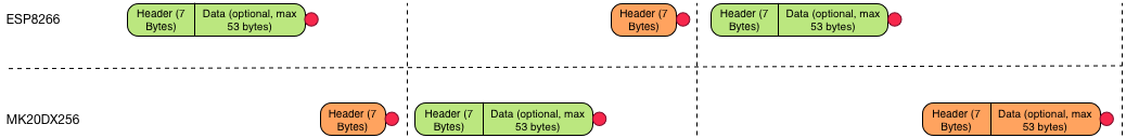
In this example ESP8266 sends a packet and received just a header (without data). After that MK20 sends a request to ESP and receives a response back – again just a header. The header probably just indicates everything ok, but that is up to the specific application and task. The last request/response shows something different. In this case, the response also contains some data.
Let’s have a look at the CommStack packet header again. It holds these information:
taskID
CommStack only handles sending and receiving structured data. The application has to work with the data and needs to know what to do. TaskID stores that. As it’s defined as a single byte (uint8_t) we have 255 different types of requests to send. Think about a task as a function call. By requesting a taskID you make the other side do something and (optionally) return something. And there are 255 function calls available. For such a small system that should be enough.
Have a look at this small excerpt of the CommStack tasks defined in Printrhub:
enum class TaskID : uint8_t {
  GetIndexFile = 1,
  GetProjectWithID = 2,
  PrintProjectWithID = 3,
  GetTimeAndDate = 4,
  GetProjectItemWithID = 5,
  GetJobWithID = 6,
  FileOpenForWrite = 7,
  FileSaveData = 8,
...
Currently in total 37 tasks have been defined. However, a few of them are reserved and not used at the moment. If you split your todos in simple pieces of work you can get away with just a few tasks. In fact, FileSaveData is used by many different application needs.
commType
CommType indicates which type of packet it is. There are three defined:
enum CommType : uint8_t {
  Request = 1,
  ResponseSuccess = 2,
  ResponseFailed = 3
};
We didn’t describe ResponseFailed yet. Responses can indicate that everything went fine or that something went wrong on the other side. I didn’t want to add another byte to the header for that (the fewer bytes the less overhead) and just defined it in the commType structure.
contentLength
Each header needs to store the number of bytes that the data section of the packet will have. As we only store small amounts of data in each packet (remember the whole packet must fit in the serial buffer of 64 bytes) the data section cannot be larger than 53 bytes. A single byte that info is enough.
checkSum and dataCheckSum
Last but not least we need some checksums. Even if you send the expected number of bytes and get a packet marker it is always possible that you receive different bytes. Sending data in electronics is nothing more than putting a signal to HIGH and LOW in predefined intervals or in sync with another signal. If any of those up and downs is not registered or gets corrupted due to noise or external influence your byte looks different. A checksum is a simple method of making sure you got everything and everything has been transferred correctly.
We have two checksums. The first checksum is the checksum of the whole packet (checkSum), the other checksum just makes sure that the data packet is intact. As the data is part of the whole packet checksum it looks to be obsolete. It is, but using the data checksum we make sure that we get the same data even after decoding them from COBS as there could be errors in encoding or decoding of the data.
In our case (small packets) we can define checksums to be just the sum of all bytes of the packet. Checksums are defined as uint16_t (two bytes) and can hold a total number of 65.536 (256*256). As we have a maximum of 64 bytes in each packet even a packet with values of only 0xFF (255) will only sum up to 16.320. If you have larger packages you will either need to increase the checksum counter to a long word for example or you need a more clever algorithm. We did not need to do that and so we kept it as simple as it gets.
An example
CommStack basically just handles sending and receiving of the packets. The application handles the sequence of packets. We started this document by having a look what happens if a user starts a print. ESP will have to download the GCode file and needs to send it to MK20 in order to store it on the SD card. Here is a small run down of what happens in CommStack.
- MK20 sends a request to ESP. The request contains the URL as the data part of the request
- ESP initiates a request to the URL, receives and parses the response. ESP reads the size from the file from the HTTP response header
- ESP sends response to MK20 and sends the file size data following the response header.
- MK20 sets up download progress bar (we now know how much data we expect to receive) and opens a file for writing on SD card
- ESP downloads up to 53 bytes from the web and sends a request to MK20 and adds the file data
- MK20 verifies checksums and writes data to SD card. If verification fails it sends a response with ResponseFailed flag back. If data is ok and written to SD card it sends a ResponseSuccess back
- ESP resends the last packet again if it receives ResponseFailed or the next data if ResponseSuccess came back
- Once everything has been sent, ESP sends a request to close the file to MK20
- MK20 closes the file and proceeds with printing that file
Wait! MK20 did not send a response in the last step!
Freedom is great
Yes, it’s not necessary to send a response. CommStack does not keep track of request and responses like a browser does. It’s just a very loosely coupled system. Both sides implement CommStack listeners and act differently to tasks if they are a request or response.
Waiting for a response is only implemented in the application. It’s not part of the CommStack system. This makes the CommStack system very flexible, but at first a bit more complicated to understand as each application part (scene or mode) has to mess around with directly with CommStack. I could have designed CommStack to implement more standard behavior or by adding another layer of abstraction between the application and CommStack. But that only makes sense if your application implements the same thing at various points in your code. As this is not the case I did not implement that layer of abstraction but just build directly on CommStack.
Have a look at the esp/DownloadFromSDCard and mk20/DownloadFileController that communicate via CommStack to download and transfer a file from ESP to the MK20 and SD card.
Dataflow II
We did not implement the standard RTS/CTS but finally we added a similar system to CommStack. Both MCUs share two additional lines that are active low. That means as long as the other sides pin is LOW CommStack data can be sent. If it is HIGH we just skip sending data and try it in the next iteration. Sometimes, MK20 is busy with updating the display and we need to make sure no data is lost. This system makes sure all data is received and processed.
Final thoughts
I think CommStack is a very powerful communication system that makes it very easy to implement flexible MCU to MCU communication via UART. It could be used for BlueTooth and other WiFi modules, too. Once you have implemented CommStack into your own application it’s so easy to send and receive data. If you couple it with the MemoryStream (another system we developed) as your data storage it’s even simpler.
If I have some time I will implement that layer of abstraction over CommStack to make it even easier to implement things like waiting for a response and automatically splitting larger data packets into pieces compatible with CommStack. Let us know if you intend to develop that and please send us Pull Requests with your additions and bug fixes.
Source code
We published source code for CommStack (and various other parts) on Github under the MIT license: Printrhub source repository. Both sides (ESP and MK20) implement the same CommStack class. There are some slight differences between each implementation but it’s mainly modifications to handle ESPs watchdog.
Disclaimer
It’s been a lot of hard work to invent and implement all that. And we are given away the source code because we believe in Open Source and the community. But of course we also need to sell our products! So, please support our work by spreading your word and by having a closer look at our store and website.


One thought on “Printrbot Simple 2016 CommStack explained”