If you have read one of my previous blog posts about building a custom Teensy you already know I have been working on a device based on the Teensy design.
Working in my lab with electronics I came across different little challenges once in a while, and noticed that I am missing tools to handle them efficiently. Just a quick list, I am sure you could add various items to the list:
- What is the I2C address of a chip? (yeah, you can work through the Datasheet but the Datasheets I know don’t have an outline topic for this. It’s somewhere hidden deep in text somewhere)
- What is the voltage range of the analog sensor in my current environment (take a photo sensor)?
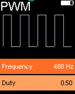
- Generating PWM or DAC signals
- Does this circuit do anything?
- Does this circuit do anything specific?
- Reading serial output of your Microcontroller/Arduino project
Of course these aren’t any issues that you could not handle with the tools you have. But each of these take time. Checking an IC for it’s I2C address is easy: Connect it to your Arduino Uno, firing up the I2C Scanner sketch and you are good to go. That is 10 minutes minimum finding your Uno, wiring it up, firing Arduino IDE, uploading the sketch. And everything while your workspace is full of components, wires and stuff for the actual project you are working on.
I had been working on wireless sensors for a while that should take the least amount of power possible. You cannot add status LEDs as they draw way too much power. I had those PCBs lying around and had no clue if they do anything. I had to carry my laptop around, connecting it to the PCB to read the serial port to see what it does.
Why, the heck did I learn all that programming and electronics stuff and not using it to solve that issue. I thought of a small, portable device featuring some ports to connect stuff like sensors and other circuits and some menu driven user interface to trigger various modules doing tests, reading data, you get it.
Announcing Little Helper!
I decided to focus on these features for my Little Helper.
- Small (iPod sized)
- Unconnected, i.e. battery powered and rechargeable
- Easy to use User Interface, i.e. TFT screen
- One handed operation
- Support for 3.3V and 5V
- DAC output
- Fast MCU
- Enough RAM for a larger software project
- Arduino compatible
- One button is enough design
Today, when building mobile devices one might think about touch displays. I decided to not use them because they do not allow for good, precise single handed operation, and I think that is an important feature for my Little Helper. The second best interface for small devices is a click wheel. Hundreds of million sold iPod seem to prove that.
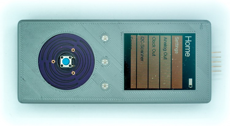
This is what I came up with:
It’s amazing how far we have come. I have been able to built this thing in my lab. This is just amazing. A few years ago a device like that was high tech. A device worth hundreds of Dollars!
ARM powered mobile iPod like device
I already knew the Teensy quite well and loved it’s power. Teensy also has support for 3.3 and 5V and there is tremendous software support from its creator. I quickly wired up the device using breadboard components I bought from Adafruit and Sparkfun. The main components I used in the design are:
- JD-T1800 (There is an Adafruit Breakout available)
- AT42QT2120 touch controller from Atmel for the clickwheel
- MCP73831 battery charge management controller (as seen in Adafruits PowerBoost Breakout)
- TPS61200 switching regulator for optimal battery lifetime (as seen in Sparkfun Power Cell)
- Teensy Microcontroller (MK20DX256VLH7 and Mini54Tan)
- FM24CL64B FRAM IC for securely saving settings and extending RAM (Adafruit Breakout)
- MAX1704X fuel gauge to measure battery level (Sparkfun Lipo Fuel Gauge)
- Custom built touch wheel (OSHPark-Project)
- One button featuring turn-on, turn-off and control
- Port for attaching sensors (GND, 3.3V out, 3 digital in/out, DAC out, 3 digital/analog in, I2C)
- 3 Neopixel RGB LEDs for status display
- JTAG Debug interface (never used it)
As you can see this device hosts all components necessary to build a LIPO powered LCD device with an ARM processor featuring nearly 100 MHz and enough RAM for more ambitious projects.
![]()
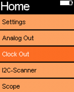
Using Little Helper
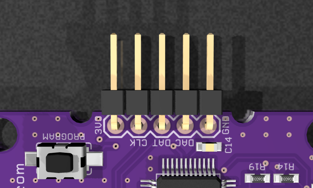
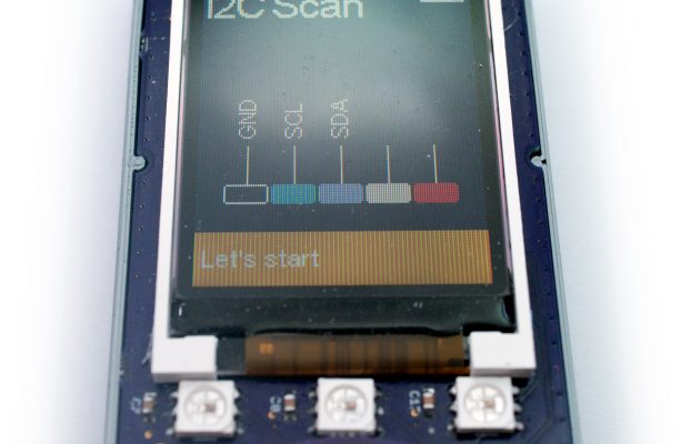
The port exposed at the top of the device offers 5 pins. These pins can be customized in software and offer various modes. You can directly attach I2C devices (breakouts) or circuits to scan I2C devices. This mode is shown in the image above. Software shows the pin assignment which makes it easy to connect the device. Click start and the scanner searches for possible addresses and lists found devices.
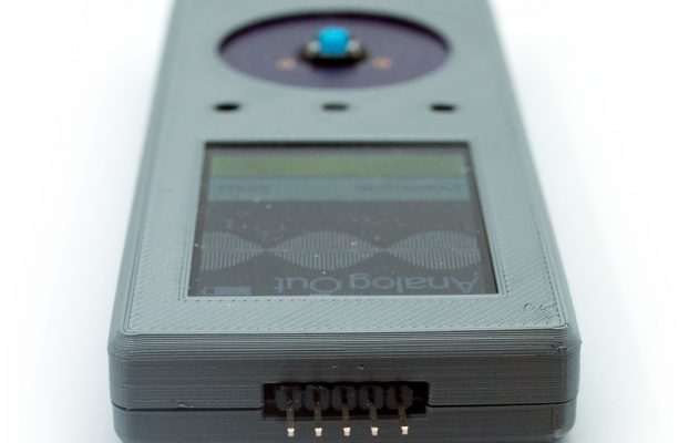
If you quickly need regulated 3.3V you can of course you the device, too. One of the pins exposes the DAC pin of the Teensy. You can use it (and the software) to deliver a very precise voltage level or even very precise audio!
And, of course by connecting serial out Little Helper shows incoming serial port “traffic”. You’ll never need to connect your device to your computer again just to read the logs posted on the serial port.
I even developed a Debug-API that does it’s own bit banging to leave the serial port for other things. Add the Debug API to your project and use it instead of the Serial port. Little Helper understands the debug protocol and shows logs as it does with the Serial port. But there is more: Using the Debug API you can control the three RGB LEDs of Little Helper. This makes it easy to show quickly show debug status without adding the necessary hardware (and code) to your project.
Open Source Hardware
I decided to open source it, because I am focussing my time to Copper at the moment. A native EDA software for the Mac. And I think the design is a good reference for others as it’s always good to have some inspiration and to see layouts and schematics of parts that are working in real world projects.
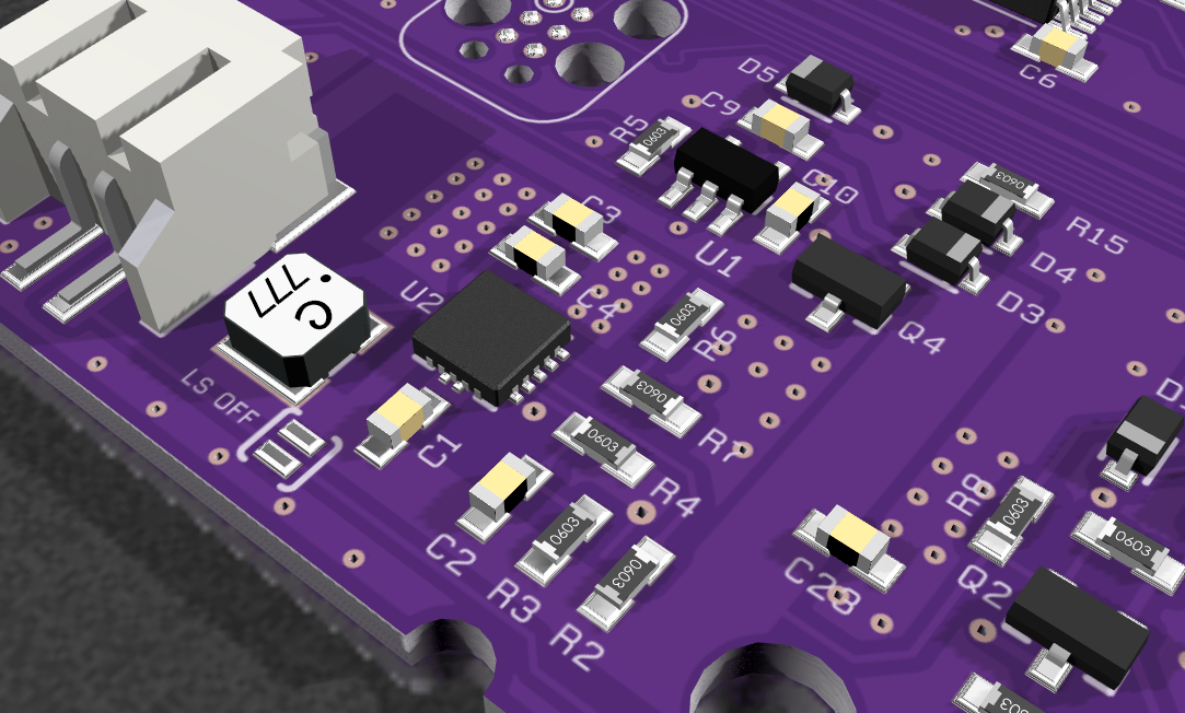
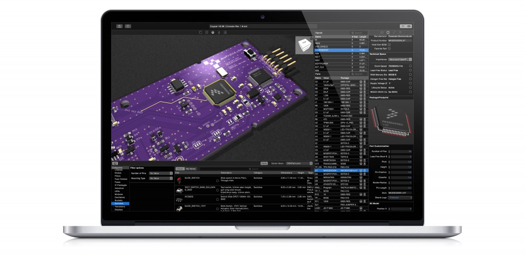
I created the design with Eagle and optimized it with Copper. Copper allows you to analyze your design for errors, creates wonderful images of your PCB as seen below and helps finding the right parts and distributors for your design. Enough of advertising for Copper. However, if you own a Mac take a look, please ;-).
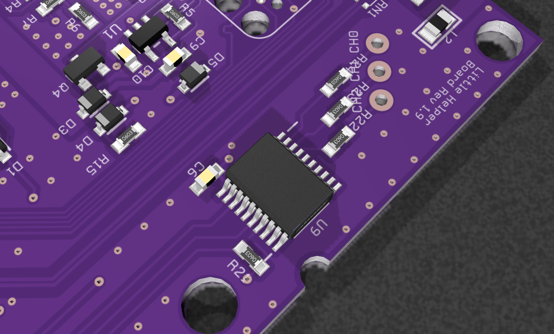
This is the layout showing the top and bottom of the PCB at the same time. The top contains all the ICs and most of the circuit, while the bottom contains the touch wheel (a small PCB also built with Eagle), the Neopixels and the LCD screen.
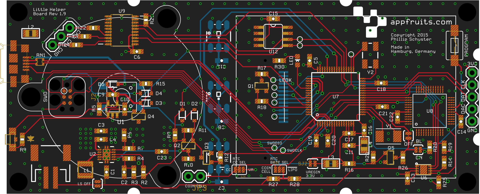
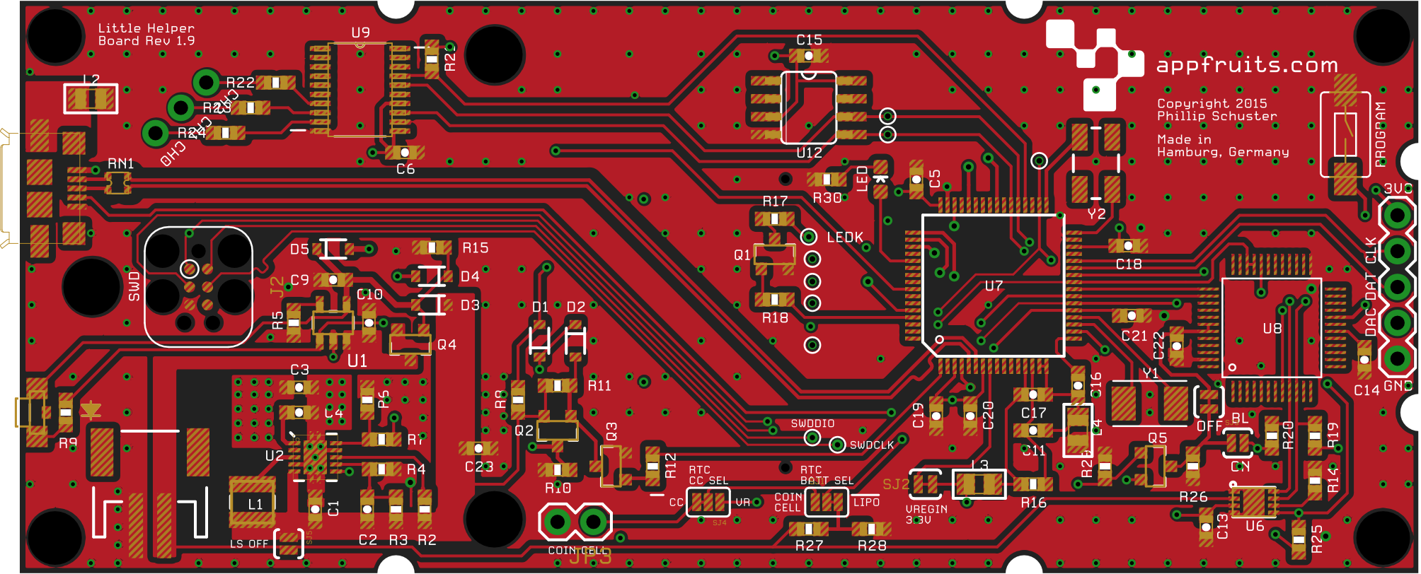
Showing the top layer with copper pours enabled shows the very important pours for the switching regulator (bottom left) that needs separated GNDs to reduce the noise level. As our device wants to connect to the outside world we have to make sure noise is a non issue and that is not always easy with switching regulators.
You can also see the differential pairs for connecting the USB to the MCU. They are length matched and isolated from the ground to prevent cross-talk. In my other blog post about building your own Teensy I go into detail into this task and how to do that with Eagle.
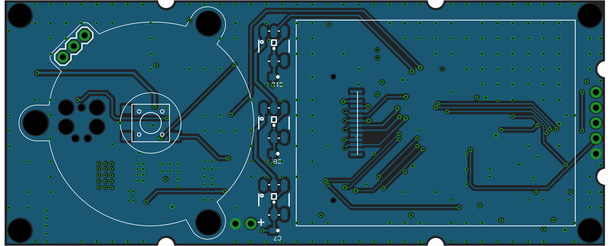
The bottom layer is much easier as it only contains a few pads. On this side we connect the LCD display, the Neopixels and the touch wheel. The Touch wheel is explained later. You can see the through hole ports for connecting the touch wheel (using male pin headers gave the correct distance) and the port pin header. I chose through hole here (also the rest of the board is SMD) because they are more robust and I didn’t want the port to be able to break away easily.
The design explained
I’ll try to explain the most critical design aspects below. Just click through the tabs to see what the different parts of the device are for and why I chose specific components. I like to place components to build blocks. This way I can easily use proven designs in my next projects. I do that in schematics as well as layout. Of course it’s not always possible in layout, but most of the time. I think of building blocks in a PCB design like APIs in software design. They have a specific interface (connected signals, power and GND) and have a very specific task and most of the time they can be used without the other parts of the circuit in another project.
The power supply system is formed by the switching regulator TPS61200 together with the MCP73831 battery charger and the button placed inside the click wheel. Pressing the button triggers the switching regulator that in turn activates the switching regulator. When long pressing the button, the software recognizes this and draws a KILL line LOW that collapses the circuit and the device turns off. See the schematics for details.
Switching regulator requires careful design as it brings a lot of noise (due to fast switching). Take my layout or that of Adafruit in its Power Cell Breakout to get a good separation between GND and power GND.
The touch controller is the AT42QT2120. I chose it, because it’s really good and easy to use. It’s easy to communicate with this device using I2C and can be used with sliders, rotational sliders (click wheel) and simple “buttons”.
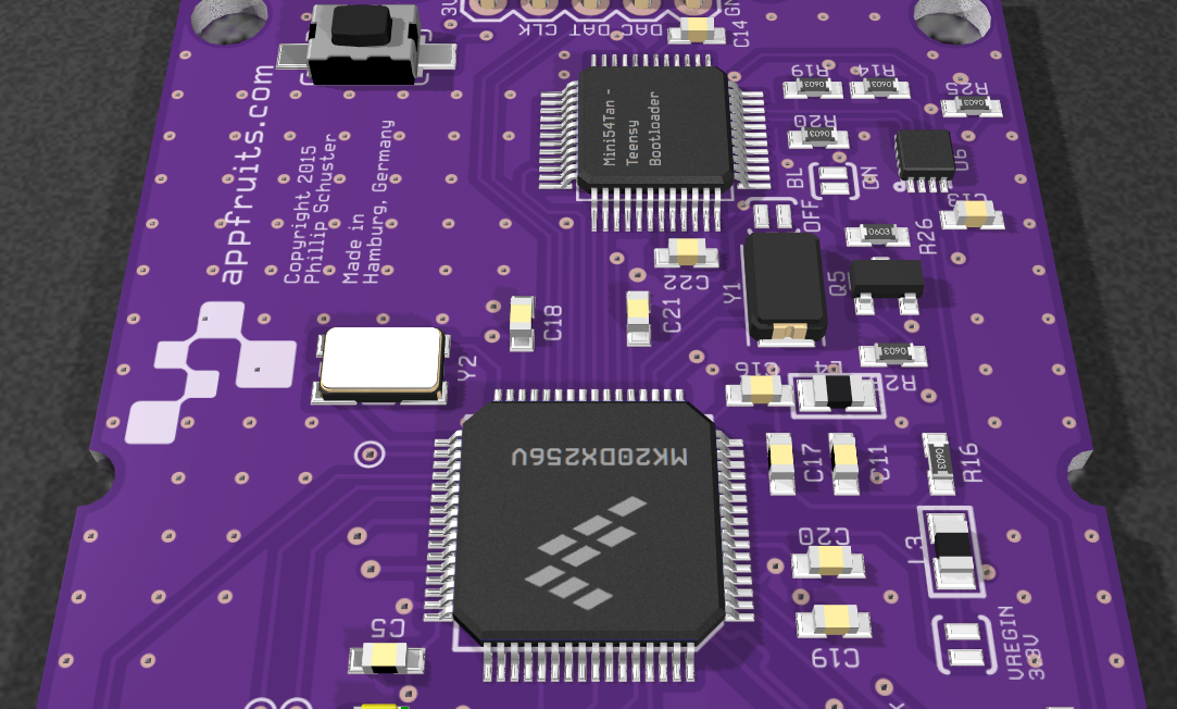
This is the whole Teensy part featuring a powerful Freescale ARM MCU with 100 MHz, 265 KB Flash and 64KB SRAM which is enough for this kind of device. I have also added the program button which is easily triggered by a special button in the enclosing (see later). This allows for very easy firmware programming. Compile the source code. Connect the Little Helper with USB to your computer and press the button. That’s it!
This part is described in detail in my blog post about Building a custom Teensy. Please note: It seems that the Mini54Tan design is deprecated now. I don’t know how long it’s supported by PJRC.com, so make sure you don’t bet on the wrong horse here!
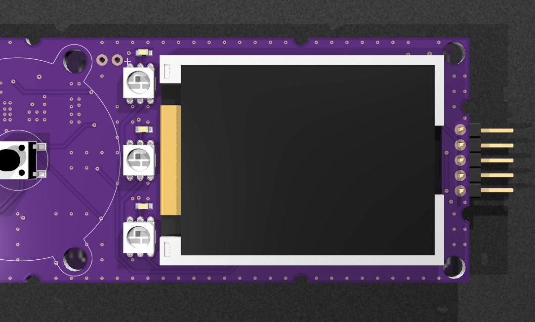
This is the JD-T1800 SPI based 1.8 inch TFT display. It’s available in various break out boards and is really nice. It’s not retina, but 128×160 pixels is more than enough for this kind of device. It is soldered directly on the PCB using a flex PCB connector. This sounds like a terrible task, but it’s really easy to do. I did fix the flex connector on my PCB with a tape, soldered it and removed the tape.
I heavily modified a Adafruit library (that is already optimized for Teensy) by introducing a back buffer. This allows for very fast update rates and even allows quite fluid animations.
![]()
The Neopixels are used to show status of the device. As they draw quite a lot of power they aren’t used very often, but they are quite useful. They can be programed using the debug protocol from outside which in turn allows simple circuits connected to Little Helper to show complex status themes by triggering these LEDs.
This port is like the probes of your scobe. They are the most important part of the design as they allow to connect Little Helper to sensor, other circuits and can be used by the firmware in a very flexible manner. You can use them to trigger I2C devices, scan for I2C devices, deliver regulated 3.3V or any other voltage using the DAC pin.
They are also used to read from serial ports.
Cool images, aren’t they? I really like them as they are so useful to show various parts of a design and don’t look as awful as the standard 2D PCB export with rectangles showing interesting parts. You can create these kind of images with Copper. Load your Eagle design into Copper and use the included, extensive 3D part library to attach 3D parts to your footprints. This is a matter of minutes for such a board. After that you can set camera angles, light, solder mask color, etc. to your liking. The PCB renders in real time. Press a button to export the image at high resolution! You can even export the 3D model to load in Fusion 360 or other mechanical CAD software to build enclosings. This is what I did here!
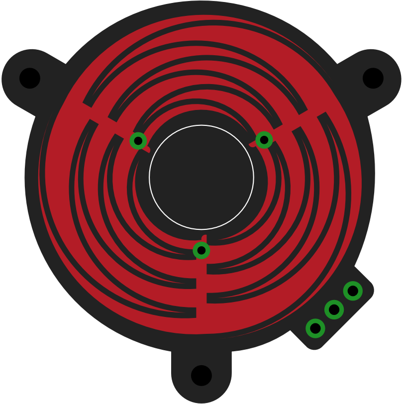
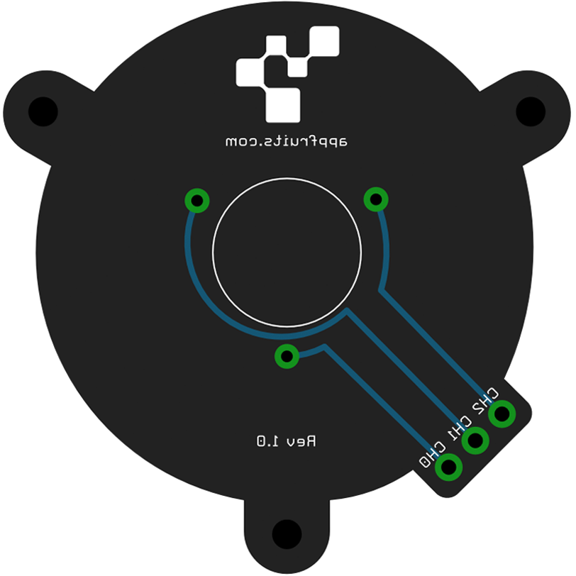
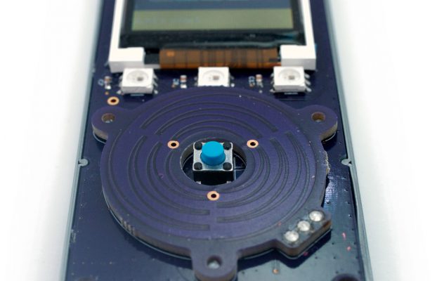
The Click Wheel
The iPod had this user interface for a long time. And I think it’s one of the best interfaces for fast one-handed operation. The Atmel touch controller also allows this kind of input, but the traces must have a very specific form to work. Look at the Datasheet if you’re interested how it works. Replicating this kind of PCB is very annoying with Eagle and luckily one guy has built a ULP before. I had to modify it, as it had a few bugs and did not work for my intended size, but I was able to fix the errors.
There are two ULPs. The first ULP qslice.ulp does create the polygons, that form the copper that serves as capacitive touch sensor. The second ULP touch_pcb.ulp does create the board outline, holes, etc. necessary to get a complete PCB. You can see the touch wheel PCB at OSHPark. You can order 3 x PCBs for $11.55 which is a steal!
If you are interested in the ULPs, you’ll find them on our Github Account.
Credits for building the base ULP goes to Dan Afonso (www.afonsoconsulting.com).
Order Touch Wheel at OSHParkThe schematics
Here are the schematics in all it’s glory. As the parts are separated in the same functional groups as above it should be easy to find the corresponding schematics for the layouts. Please post in the comments section below if you have specific questions. I will try my best to answer them and give advice!
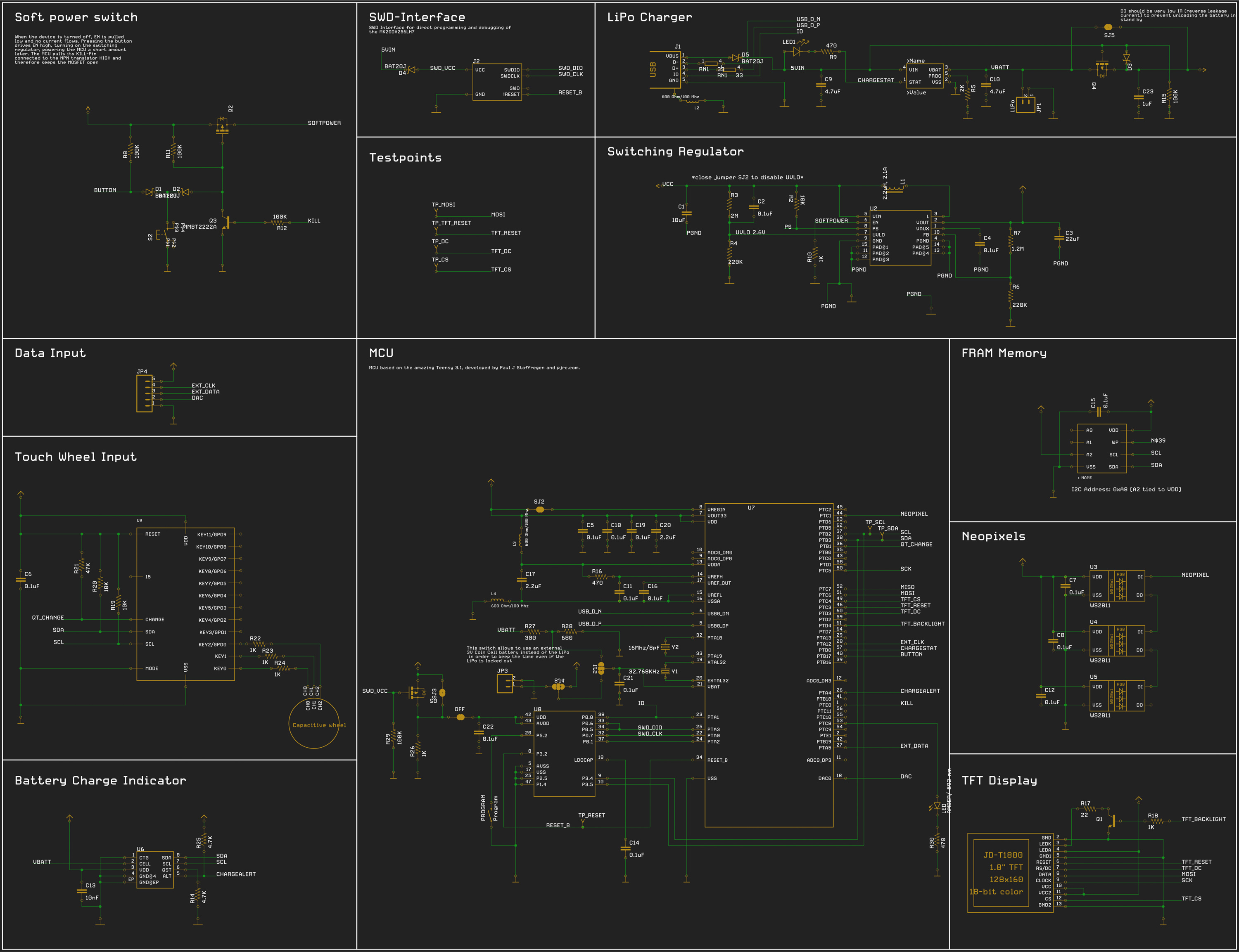
If you try building your own design based on this one: Please leave the MCU section as it is. It’s quite hard to get it right. I needed two revisions to get it running as you have to be very careful when wiring up the MCUs. You will also have to follow a few PCB layout guidelines. I have written them down in my previous blog post about Building your own custom Teensy.
BOM
Schematics often are not very specific which device to choose from the long list of available devices. Because I don’t really like part sourcing, I added part sourcing tools to Copper. Octopart.com is directly built-in and makes it easy to search parts and keep selected part numbers in a save place – directly connected with your design. Later, when it comes to ordering the parts, Copper finds prices and availability for all your parts and exports a BOM file that you can use to order at Mouser, Digi-Key, and various other distributors. I really like Mouser as they deliver fast (to Germany) and typically have the parts in stock I need.
Here is the complete BOM for all parts. A few parts aren’t available at the standard distributors like Digi-Key or Mouser. Those are sold by Adafruit or Sparkfun. Both have quite a lot of resellers around the world, you should be able to get those parts.
| Quantity | Value | Case/Package | Parts | MPN |
|---|---|---|---|---|
| 15 | 0.1uF | 0603 | C18, C19, C2, C4, C5, C6, C7, C8, C11, C12, C21, C14, C22, C15, C16 | C0603C104J3RACTU |
| 5 | 100K | 0603 | R29, R8, R11, R12, R15 | ERJ-3EKF1003V |
| 1 | M05PTH | JP4 | Sold by Adafruit | |
| 3 | 10K | 0603 | R2, R20, R19 | ERJ-3GEYJ103V |
| 1 | 2M | 0603 | R3 | ERJ-3GEYJ205V |
| 1 | AMBER/ 592 nm | 0603 | LED | HSMA-C190 |
| 2 | 220K | 0603 | R4, R6 | ERJ-3GEYJ224V |
| 1 | 10uF | 0603;1608 | C1 | GRM188R60J106ME47D |
| 1 | 32.768KHz | Y1 | FC-255 32.7680K-A3 | |
| 1 | 2K | 0603 | R5 | ERJ-3GEYJ202V |
| 1 | 16Mhz/8pF | Y2 | ECS-160-8-30B-CKM | |
| 1 | 22uF | 0603;1608 | C3 | GRM188R60J226MEA0D |
| 1 | 1.2M | 0603 | R7 | ERJ-3GEYJ125V |
| 1 | 1981584-1 | J1 | ZX62-AB-5PA(11) | |
| 1 | MCP73831 | SOT-23 | U1 | MCP73831T-2ACI/OT |
| 3 | 470 | 0603 | R9, R30, R16 | ERJ-3GEYJ471V |
| 1 | TPS61200 | SON | U2 | TPS61200DRCR |
| 3 | WS2811 | U3, U4, U5 | ||
| 2 | SOT-23 | Q1, Q3 | MMBT2222ALT1G | |
| 2 | 4.7uF | 0603;1608 | C9, C10 | GRM188R60J475KE19D |
| 3 | MOSFET-PCHANNEL | SOT-23 | Q2, Q4, Q5 | BSS84LT1G |
| 1 | MAX1704X | U6 | MAX17048G+ | |
| 1 | FM24CL64BSOIC8_150MIL | U12 | FM24CL64B-GTR | |
| 1 | MK20DX256VLH7 | U7 | MK20DX256VLH7 | |
| 1 | MINI54TAN | U8 | Sold by PJRC.com | |
| 1 | AT42QT2120_COMMS | U9 | AT42QT2120-XU | |
| 1 | Program | PROGRAM | RS282G05A3SMRT | |
| 6 | 1K | 0603 | R10, R22, R23, R24, R18, R26 | ERJ-3GEYJ102V |
| 1 | JD-T1800 | LCD1 | Sold by Adafruit | |
| 1 | 47K | 0603 | R21 | ERJ-3EKF4702V |
| 1 | 2.2uH; 2.1A | L1 | LPS3015-222MRB | |
| 2 | 4.7K | 0603 | R14, R25 | ERJ-3EKF4701V |
| 3 | 600 Ohm/100 Mhz | 0805 | L2, L3, L4 | BK2125HM601-T |
| 2 | 2.2uF | 0603 | C20, C17 | C0603C225K4PACTU |
| 1 | 33 | 0603 | RN1 | EXB-34V330JV |
| 1 | S2 | PTS645SH50SMTR92 LFS | ||
| 1 | 10nF | 0603 | C13 | C0603C103K5RACTU |
| 1 | 22 | 0603 | R17 | ERJ-3GEYJ220V |
| 4 | BAT20J | SOD-323 | D1, D2, D4, D5 | BAT20JFILM |
| 1 | QTWHEEL_MODULE | U$1 | Custom PCB, order at OSHPark | |
| 1 | LiPo | JP1 | Sold by Sparkfun | |
| 1 | DIODE-SCHOTTKY-LOW_LEAKAGE | D3 | ZLLS410TA | |
| 1 | 1uF | 0603;1608 | C23 | GRM188R61E105KA12D |
| 1 | 300 | 0603 | R27 | ERJ-3EKF3000V |
| 1 | 680 | 0603 | R28 | ERJ-3EKF6800V |
| 1 | 597-2311-407F | LED1 | 597-2311-407F |
Fails
Of course I had fails while building this device. I don’t want to recap them in this blog post in detail, but if you are interested in them, here is my original post in the Teensy forum with detailed analysis from my side and a lot of help and explanations from others.
Downloads
What I really love about Copper is it’s file management. We want Copper to be a part of your workflow. To be successful it’s absolutely necessary that file handling is a non issue. You don’t want to fiddle with overwritten files and all that stuff. So we designed Copper to generate a third file along the typical Eagle .brd and .sch files. We named it .cop. This file holds everything you attach to your original Eagle design while working with Copper.
Copper never changes the original Eagle files, but needs them as a reference. If you save your work in Eagle, Copper recognized that and updates its own representation of the board with the new one. All settings for parts like part numbers or attached 3D models is kept. This makes sharing very easy – as you can see here. If you open the files in Copper provided below, you will have all the information attached to the board like the complete BOM, Prices and Availability from distributors like Digi-Key, Farnell, Mouser and a few others with the click of a button. Yes, one click! You will also see the same 3D model shown above. And you can navigate the board as I have set presets for the various camera views. All 3D models are kept in the Copper Cloud. So we don’t need to add large files to the .cop file. Copper downloads models in the background when needed from Copper Cloud.
Download PCB Design and FirmwareThe housing
Of course I wanted to build a device that is usable. And as such it must have an enclosing. I own a 3D printer that allows me to build such things very easily and cost efficient. But building an enclosing is not so easy. I really recommend doing it with (real) CAD software. My favorite is Fusion 360. It’s awesome but that is a different story.
I exported the Eagle design with Copper as a 3D model and imported it into Fusion 360. This way I could built a very precise enclosing that really fits the PCB. I only needed one iteration until everything did fit very nicely! There is no chance to build good enclosings without a very good 3D model of your PCB. Copper creates them by taking into account precise dimensions and form of each and every part as Copper has hundreds of components that are included and are the CAD models directly from the part manufacturers.
I have made my Fusion 360 project public. It’s easy to inspect the design there. You may also just download it and print it on your 3D printer. It should print good. But you will have to print in high detail. Please also note that the walls are optimized for a 0.4mm nozzle. You may need to adjust it if you intend to print on a different nozzle size.
Have a look at the enclosing design here: http://a360.co/1QneZ3d. This is the Fusion 360 embedded viewer. It should display the enclosing directly in your browser. If it does not work give the link above a try.
Please note: Home position in this project shows the housing from the bottom. I messed up the orientation so you’ll have to rotate the 3D model a little bit to see it from the top. But you can see the program botton in the top left area of the bottom housing. This allows for easy firmware flashing.
Download Housing CAD modelThe Software
As said before flashing the firmware is very easy to do. Thanks to the awesome Teensy Bootloader built-in. There are quite a few hardware components that we have to support with software. I wanted a nice user interface. A fluid and intuitive one. As I am developing software my whole life I have come to love good structure and readability. And the single most useful structure today for programming user interfaces is MVC. I have been using this structure in this source code, too.
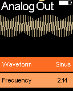
The software is structured in modules, that are accessible from the main menu. I though of having a lot of useful small modules that each provide a very specific functionality like an I2C scanner or analog out, even a small scope showing analog voltage over time.
I have added standard controls that you can use and which are bound to the built-in hardware. A button for example is focused by “rotating” the click wheel until its highlighted, pressing the button activates it. A “slider” is like a button, but pressing it lets you choose a value between a min and max value by rotating the wheel. Creating new modules is just a minute of Copy and Paste for UI and writing the code that does the real work.
The software also has a built in screenshot feature. This sends a screenshot in raw bytes through the serial port. I have written a small OS X application that reads the serial port and encodes an image out of the data. If you are interested in the screenshot project, drop me a line.
Here are a few screenshots from the firmware running on the device.

The software is available under a MIT license at Github. Have a look!
Download Firmware Source-Code
Copper
If you like what we do, please support us! This has been a test project to test and develop the functionality of Copper. Hardware is hard, and this project is no exclusion. I needed two hardware revisions to get the board fully functional. This takes time and money. I have created a software that allows you to find errors by providing tools beyond ERC and DRC and also allows for awesome visualization of your board. I really like this way to document and showcase your hardware project.
It is Mac exclusive (10.10+). I am sorry, there is no Windows and/or Linux version! It’s available for purchase for only 24,99 EUR/USD and is available in Mac App Store or our own website.


Dare I ask, why the MINI54 rather than MKL02 based bootloader?
When I started the project Teensy 3.1 with the Mini54 was state of the art. I finished the project in March 2015 and decided to release it to the public a few weeks ago. Today, I would start with the MLK02 bootloader as Mini54 is deprecated.
It will be necessary to update this project to the new Teensy Boot loader, and I will look into that. If anyone is interested in doing that, please let me know as it makes sense to coordinate work here.
What would be the pro of upgrading this component? What would be the extra work? More code and new traces? I am thinking of building one, but not sure if it worth upgrading.
Hi,
there is not much to do. The only thing to do is replacing the old bootloader chip with the new one. This requires a few traces routed and perhaps a few traces rerouted.
There is no benefit at all. It’s just to make this product future proof as the old bootloader chip is deprecated, means that once its sold out you won’t get them anymore. As far as I know PJRC have a few left. If you are only interested in building a few then I would suggest ordering a few chips and building the device. If you want to use the design for your own mass market project I suggest upgrading the design.
If I have time (that I don’t have at the moment due to various projects) I want to upgrade the design of the LittleHelper. But that may never happen, so don’t wait for it.
Cheers,
Phillip
This is just “WOW” ! I love it.
Just one thought on the header. If you would use a female port, there is less risk of pins getting bent or braking off.
Everything else looks perfect.
Also congratulations on Copper. I recently bought it and it’s a great tool.
Thank you so for your feedback. Using a female header is a good idea. Thanks for purchasing Copper. Would you be so kind to rate it in the AppStore. This would be very helpful.
Best,
Phillip
Dear Phillip,
I absolutely love your Little Helper project!
I am in the process of building a device of a similar, iPod-like form factor (digital gym assistant), with OLED, buttons, etc.
One part I am still missing in the design is the battery (LiPo), so I want to ask: What LiPo did you use? How does it fit in your insanely thin case? I see no screenshot/photo of the battery and there is no mention of it anywhere in the description. This info would be hugely appreciated! Thanks!
Hi Daniel,
thanks so much for your kind feedback. In my project I used small LiPos sold by Adafruit (https://www.adafruit.com/category/889). The charging circuit used in LittleHelper can only charge lipos with one cell, but that shouldn’t be a big problem as you want a small LiPo.
Hope that helps.
Cheers,
Phillip
Hi,
Thank you for sharing your great experience and insight.
I just followed this guide and I made my own teensy-based board finally 🙂
Everything seems fine with my board except quiescent current consumption during shutdown.
So I measured current consumption and I observed constant quiescent current consumption about 5mA ~ 10mA.
I think it supposed to consume several tens of uA in total during power-off even quiescent current consumption of TPS61200, MCP73831, MAX17048, teensy RTC, and others is taken into account.
I tested it with two boards and I see very high quiescent current consumption in both.
Can you guess that what’s wrong with my boards?
Hi Tony,
thanks for your feedback. I also noticed, that my LittleHelper standby time is not the very best. But I don’t think it is that worse. The circuit responsible for the single button action is called a soft latch power switch and I learned a great one here: http://www.instructables.com/id/Soft-Latch-Power-Switch-Ardweeny/. This is the circuit I used in LittleHelper. There are some comments that discuss standby power consumption. It mainly depends on the parts you chose. Did you use the same parts as I promoted in the BOM or did you choose your own parts? You will need high quality parts to make sure there is as less leakage as possible.
Are you sure anything consuming power is “after” the soft latch circuit, i.e. really shut off during stand by time.
Hope that helps,
Phillip
Yes, I used exactly same parts you listed in the BOM.
And I also double checked that there is no part consuming power behind the soft latch circuit.
Does “high quality parts” you mentioned also indicate that more accurate resistor? (like 1%)
Thank you for your help 🙂
Cheers, great stuff, I like.