Over the past few months I have developed the LCD component of the new Printrbot Simple 2016. In this post I want to explain how the display system works. It makes sense you read the Behind the Scenes report of building the Simple 2016 first, as that gives you some context to what I am talking about here.
Early on we decided to use a display with the ILI9341 display driver chip as there is a very fast display driver available. We also decided to use the 2.8 inch display as this had the best fit in the new Simple model. We also decided to use the FT6206 touch screen although this can be easily exchanged as most touch screens are connected via I2C and the protocol is very simple to implement.
Adafruit has exactly this display as a break out board available. PJRC also sells the same display, but with a different touch controller. However, it’s not an issue to adept our code to another touch controller. And, of course there are display modules available at eBay. Just make sure your display has the ILI9341 display driver chip installed. Although our display system is very flexible you get best results if you choose a 320×240 pixel display to get quick results.
How displays work
Displays have a memory area and small pixels are connected to this memory (not in a circuit kind of way but you get the idea). When you change the bytes in that memory area the display reflects that. You modify this memory area using SPI to write data in specific memory regions. That takes time. And as the display immediately reflects any changes you can see the display building up the final user interface. Worst, you cannot just first fill a rectangle and then draw some text on it, as it would result in flickering. Animation is practically impossible although Paul did a very good job of making it as fast as possible.
There is a very easy way of fixing that: a back buffer. You store a memory area in your MCU that mimics that memory area of the display. You make changes there, you can overwrite data multiple times. And when everything is composed you send the whole area to the display. This does not allow for fast animations, too. But you get a nice, polished look and feel. But, Teensy does not have enough memory to store a back buffer!
Layers to the rescue
Solving issues in tight constraints is what unleashes our creativity! I finally came up with a good idea. The idea is this: If split the display in a mosaic of rectangles so that every pixel of the display is exactly occupied by one rectangle we make sure that we have no overdraw and thus we don’t have any flickers while updating the display. Here is an image of one of the sketches I made and which shows the core of the idea.
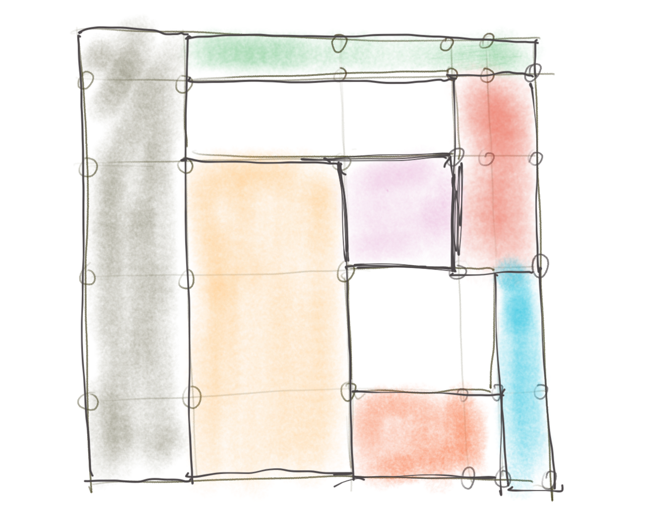
I called these rectangles layers. So each screen you see on the display is composed of various different types of layers that in total make up the exact amount of pixels of the display (let’s keep scrollable area besides for now). Each layer must be opaque,the display system doesn’t permit transparency as this would break the rule that we don’t want any overdraw, but we can simulate that. More on that later.
We have these layers at the moment:
- Text layer with foreground and background colors
- Vertical text layer with foreground and background colors
- Simple rectangle filled with color
- Bitmap coming from memory (SRAM and constant program memory)
- SD Bitmap coming from SD card
Using these building blocks we can change UI without any overdraw. As the display content is structured this way, we don’t store individual pixels in memory that would eat up our memory, but we just store areas that we will fill that area with pixels later. As this is very memory efficient we can build very, very large scrollable screens, too! And by using this structure we can even implement very fast refresh rates as we don’t need to refresh layers that haven’t changed.
Consider one of the layers being touched. We just need to change its background color and invalidate it. In the next draw call only those layers get sent to the display that changed.
This works great if you don’t change the structure of the display. What if one of the layers should move? Imagine that touched layer is a button and should move down a bit to mimic the effect of a being pressed down. To solve that, the display system keeps two separate layer structures, one background and one foreground layer system. The foreground layer system is the system that is currently visible on the display, the background layer system is what is composed during one frame (like a back buffer described earlier). Once the background layer system has been finally composed (think of the system changing the y-position of the layer being pressed down) it’s sent to the display system to finally draw to the screen.
The display system goes through each foreground layer and intersects with each layer of the background system. If the background layer didn’t change any bounds of the layers these intersection tests would fail, as each foreground layer is exactly the same as the background layer. But if bounds are changed in the background layer these intersection tests would finally deliver a few results. We just need to invalidate each layer that intersects so we draw it again in the next draw call.
It might take some time to wrap your head around that, but it’s basically very simple. The illustration below shows this process in more detail.
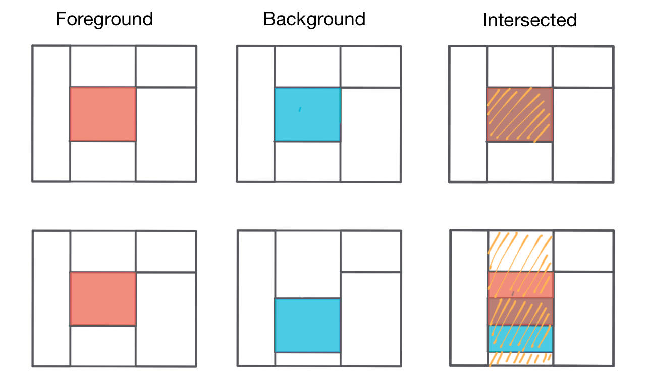
As you can see in this illustration even if things are moving around, only parts of the display need to be refreshed. The current system does not really optimize it to the end, though. You could invalidate only parts of the surrounding layers, however the current implementation just invalidates all layers affected by the updated layout.
This sounds, good. But building up layout like the one above for a lot of different screens would be quite a lot of work. We need to have an algorithm that generates these layouts on the fly.
Views to the rescue
As layers are the building blocks of our system, we need a higher level of organization. I call them Views. Views are composed of one or more layers that form the shape of the view and are the building blocks of the user interface system. At the moment we have these views:
- BitmapView (Basically just uses the BitmapLayer to display its content)
- SDBitmapView (Just uses SDBitmapLayer)
- View (Base class and single color)
- ProgressBar
- BitmapButton (Button with bitmap)
- LabelButton (Button with text)
- LabelView (Text area)
Each view has a position on the canvas that we display on screen. Views can be positioned everywhere and don’t need to align perfectly like layers need to. You can have a single user interface with a button in the middle. In this case you would position a LabelButton and that’s it. Every view is responsible to fill it’s area with layers, the display system fills the gaps between the views.
Think about that LabelView. You want to align the text in the view area and there should be some gap around the button. Another illustration shows you what’s going on when LabelView sets up its layer structure.
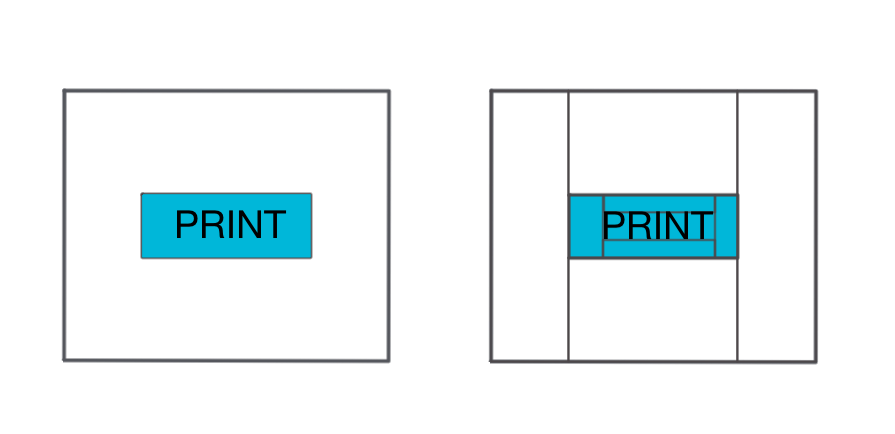
The print button is setup in the middle of the display as you can see on the left side. On the right side is the final layer structure generated for this user interface. The view is composed of five layers. Four rectangle layers for the outside of the button forming the padding of the text. By adjusting these rectangles you could make the text left, right or center aligned in horizontal and vertical position. And a text layer is positioned in between with the same background color as the view (and the surrounding rectangles). It looks like the text is composed with the background, but it’s not. It’s a clever fake.
By early setting some rules, you have to find ways to solve your needs by not breaking these rules. This unleashes creativity and well structured, good solutions!
Try to think a moment about the way I could have implemented the progress bar? It’s really easy (in our case as UI is very modern, i.e. simple and flat). We just use a very limited amount of building blocks but can form very complex user interfaces that are easy to layout and very fast to render which is the process of producing final pixel colors that are finally sent to the display.
We developed a user interface for a 3D printer, so we had quite a few user interfaces. There is the project selection, changing filaments, setting up WiFi and many other things. We needed another higher organization level.
Scenes to the rescue
Last but not least, we need to have another structure above that handles all those views in a user interface: I called them Scenes or Scene Controllers.
If you have ever been developing for iOS, this should sound familiar. And of course it is. The MVC system Apple uses for it’s operating systems is great. It’s well structured, easy to expand and works great. It always makes sense to have a look at other successful systems. They are successful for a reason!
A scene controller manages one scene at a time. A single scene must handle the whole display. Only one scene controller can be active and is responsible for handling views and also handles touches. Each scene has its own loop function that is called each frame. This scene controllers not only handle user interface, but they also do some real work.
Each scene has a few standard functions that are called in different states of its life cycle:
- onWillAppear
- onDidAppear
- loop
- onWillDisappear
- handleTouchDown
- handleTouchMoved
- handleTouchUp
By now you should get a feeling how I organized the system. There must be another system that handles scenes and calls these functions: That’s the Application. The application organizes a stack of scenes, reads touch states and calls the functions in the active scene controllers. But more on that later.
Simple 2016 has quite a few scenes, to give you some examples
- SettingsScene
- PrintStatusScene
- ProjectsScene
- JobsScene
- LoadFilamentScene
- UnloadFilamentScene
- PreheatExtruderScene
The idea behind a scene controller is that it does a very specific task and displays a corresponding user interface to give some feedback and control opportunities to the user.
Think about that PreheatExtruderScene. This scene sends a command to the printer to heat the extruder to 200°C and displays a progress bar showing the progress of heating up the printer. In its onWillAppear function the heat command is sent to the printer and progress bar is setup. Max value of progress bar is set to 200. In its loop function the PreheatExtruderScene reads the current status report from the printer, extracts the current temperature and sets the current value of the progress bar, which itself processes that by adjusting its own layers to form the new shape of the progress bar. When temperature is reached, the scene controller either pushes Load or Unload filament scene on the display stack. The application calls the onWillDisappear function of the PreheatExtruderScene, after that it calls the onWillAppear function of the Load or Unload filament scene and after that the loop function of the next scene is called.
The Application
In your typical Arduino sketch the application is the sketch, it’s composed of two functions, setup and loop. Our Application object is basically the same, but it’s a bit more structured in a C++ way of doing things, but it also has a setup and loop function.
In it’s setup function the Application sets up GPIOs, drivers and a few other things. It’s more interesting what happens in its loop function. This is a rough overview of what happens in the loop function:
- Call loop functions on various sub systems like CommStack, Printer, LEDs, Animators
- If a background job is active, calls the loop function on the background job
- If another background job is pushed to the stack, close the old job and make the new one the active one
- If a new scene is on the stack, close the current one and start the next one
- If a scene is active, send current touches to it
- Call loop function on the current scene
- Update layout
- Send layout to display (only layers that changed are sent)
A background job is basically the same as a scene, handles some work over time, but does not have any output. A background job also has a look function that is called each frame.
This structure permits our application and user interface to do a lot of things at the same time. While you touch the display and virtual buttons get updated to give some response, a file is downloaded in the background or the status reports of the printer are received.
Of course, on our small microcontroller we only have one main thread. We fake multithreading by having a stack of different items that get a loop function called regularly. But our system is not able to pause in a loop function and go on to the next like your PC/Mac can do that. Thus we have to be very careful with our loop functions. We can not use blocking functions as they would stop the whole system. Touches wouldn’t be received and printer would not receive new commands.
Quite a lot of APIs available for Arduino don’t handle that well. This simple line would kill our whole system:
Serial.readBytesUntil('\n');
This API reads the serial port until it receives a line terminator byte. If nothing is in the buffer, because the other side hasn’t send any data it just waits. In your typical Arduino sketch application this is a non issue, because your sketch does not have anything to do until the line is fully read. But our device has a lot to do, it cannot afford to wait.
If you read through the source code you might think: Why do they do that so complex? There is that simple call available. Do these dump people didn’t know that? Of course chances are that we in fact didn’t know about that simple and effective method of doing things, but chances are higher it’s there for a reason! We don’t want to block our main application loop. A good example for a rather complex implementation of a simple task is the Printr class which communicates to the printer.
Layout algorithm explained
Wow. Still reading! If we recap the application loop there is one thing we didn’t explain so far, but it’s the most important thing for our system to work fast and reliable: Update layout.
I wanted to create a framework, that permitted other members of the team to build user interfaces fast and easily. If every single scene is hard to setup, development time is so much longer. Using our framework we were able to build new scenes with full functionality with a few lines of code! To make this work, we need to setup the layer layout structure for each scene with an algorithm.
This is the hardest part of the whole system. But it’s still quite easy if you reduce this very complex problem in smaller parts. Programming is basically just that: Reduce complex problems in single pieces you can handle. The preferred way for me is to sketch things down. I sometimes even build things in Lego to visualize the issue.
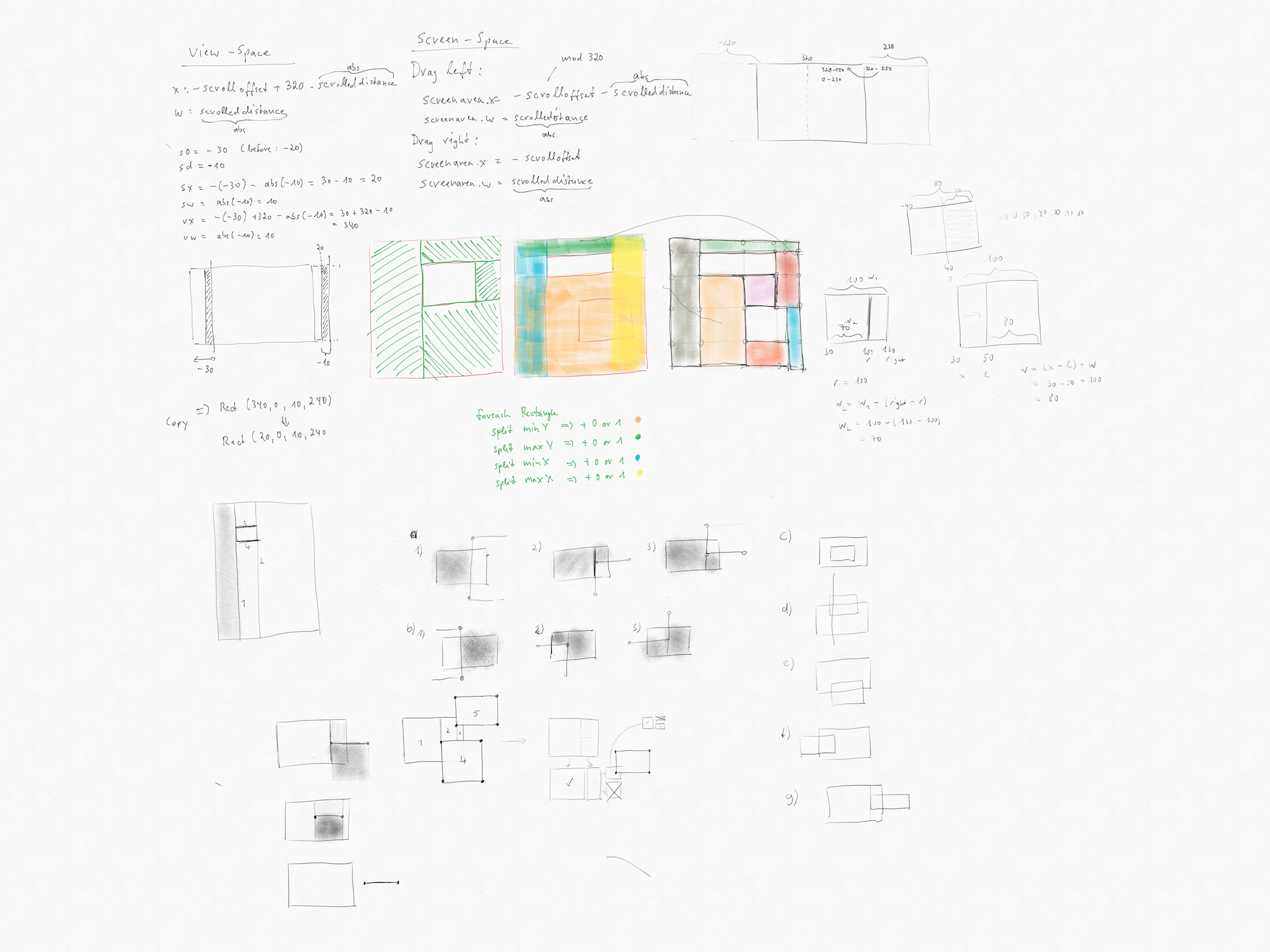
The next illustration shows how the auto layout system works. Consider a rather easy scene which is composed by three BitmapButton views. I didn’t visualize the layers inside the BitmapButton views to not confuse you. At first, the layout system asks each view to add it’s layers to the layer stack. This is done in the display function of the view.
I told you before there is a foreground and background layer. The background layer is the layer that is composed with everything needed to show the next frame and is then sent to the display. So we first need to compose that layer. That layer is a simple rectangle layer getting the background color of the scene and is as high (240) and wide (320) as the display (240). If the scene is wider than the display (scrollable) the background layer is expanded accordingly.
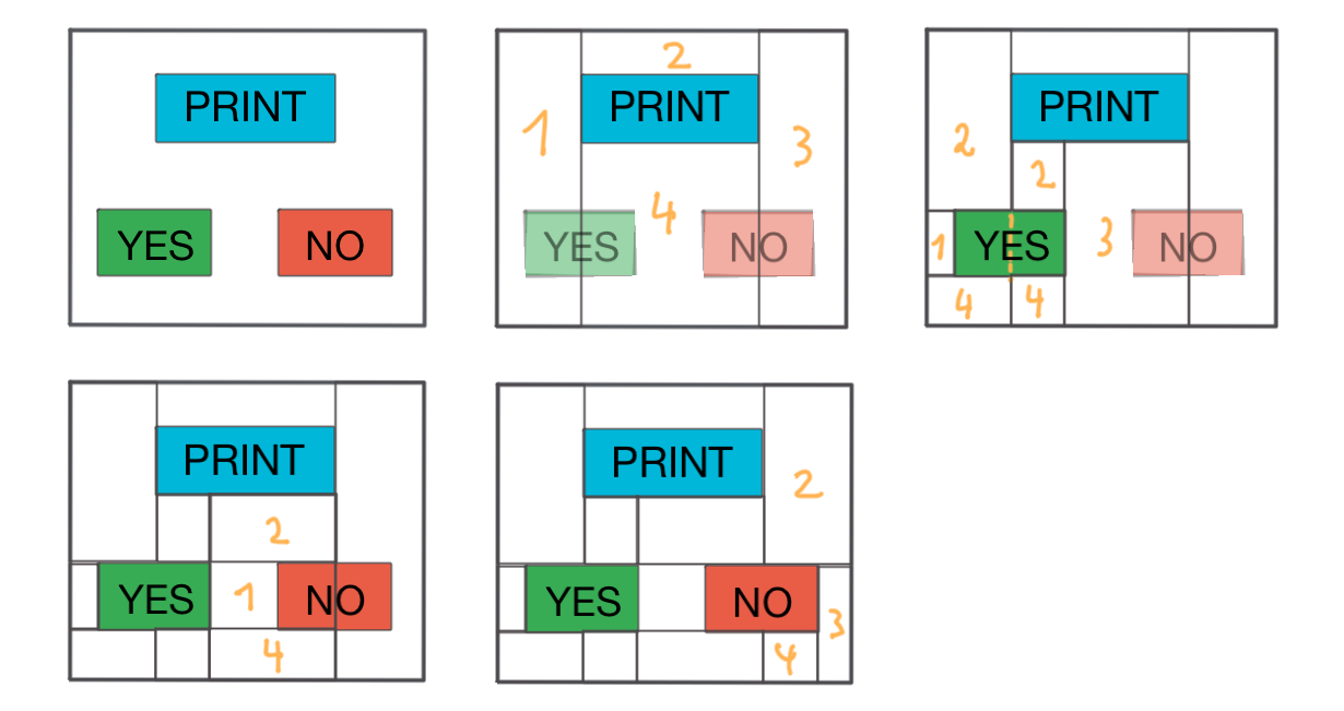 This background layer is now intersection tested against every available view rectangle in this scene. In this example the white background layer intersects the blue PRINT text layer. If they intersect, the magic happens: We split the first layer in a way that cuts out the area occupied by the second layer. We do this with a very simple algorithm. We basically create four surrounding rects: 1,2,3 and 4. In the next iteration we test every available layer against all views. Layer 1 (just created) intersects with the YES view. So, the same thing happens again: We split layer 1 using the same algorithm before. We create layer 1,2 and 4. 3? You may ask? Well, 3 does not get any area, as it has a width of 0, so it gets disposed. In the next Iteration layer 4 of the first iteration also intersects with the right side of the YES view. So we split that again. But we dispose 1 as it gets 0 width in this case. As you can see, by following this very simple algorithm we are able to split the layout into smaller pieces and stick to our rules: No gaps, no overlaps. Now, in the next iteration we have layer 3 (image 3) is splitted against the NO view again forming layers 1,2 and 4 as 3 gets disposed due to 0 width. In the last iteration we split layer 3 of image 2 against the right part of the NO view again forming layers 2, 3 and 4, one gets disposed due to 0 width.
That’s it! We have split the layout in smaller pieces! Looking at the code you can see that we have a hierarchy of layers there. As this is a recursive tree problem, it’s easier to put it in the right data structure. Having trees makes it much faster as we can leave out certain parts of the tree as they cannot be part of the next iteration. There are various methods to implement this algorithm, have a look at the code to see how I implemented it.
Hardware scrolling
There is only one thing left! Scrolling. Scrolling means, that you basically have to refresh a very large part of the display each frame. Although we have developed a great system to handle display setup and rendering, we still are not able to refresh the whole display with refresh rates that allow for fluid touch based rendering.
But, most displays feature a simple trick to implement scrolling. They have a register (small memory area) that holds the start line of the display. Typically this is at line 0. But, you can set it to any value between 0 and 320 (We scroll horizontally). What happens is that when you modify that line start parameter you move the content of the display around which is very fast.
But, if you set the line pointer value to 10, then the first display pixel row is created with pixels from line 10 in memory. You move the display content to the left. But what happens to the 10 pixels moving out of the display on the left side? They are shown on the right side, thus just wrapping the content
What you have to do now is this:
- Move the display content, let’s say by 10 pixels. This moves the display content to the left
- Now redraw the 10 pixels moved in at the right side
This is much more complicated in code as you always work in the same memory area which is shown on different areas of the display, depending on the line pointer position. We also need to refresh the freshly visible area very fast so we don’t have any graphical glitches. If you film the display at 200 FPS using your smart phone camera you can see what really happens.
Our layout system only invalidates and sends those layers to the screen that are in the invalidation rect of the current frame. If you scroll one pixel to the left your invalidation rect is only 1 pixel wide (on the right side). So only those layers that are in this area are sent to the display. And we only send those pixels that really lie in that invalidation rect.
As you know the layers are structured in a tree structure. You can now see why. Take our example above. The layout is formed by 4 layers splitting the layout in 4 major areas. These areas are splitted by the YES and NO buttons. Take layers 1, 2 and 4 from the second image. Those would not intersect with the intersection rectangle at the rightmost corner of the display. As the sub layers are always within its parent layers we do not need to test all the little layers that are later formed from these layers as they cannot intersect. So we only need to have a look at layer 3 which is in between the right most invalidation rect. This way we can test against the validation rect very fast. Having layouts that are thousands of pixels wide and formed by hundreds or thousands of layers, it would be very inefficient to test every small layer against the invalidation rect. In the first test iteration we can get rid of 99% of all layers very fast and only concentrate on a very few.
Final thoughts
Still reading! Great. Thanks for your interest. If you made it up to this point you should have an understanding that a lot of development went into this system and we really hope that you can make good use of it.
It’s not a final framework though. A few parts have been working fine for the specific user interface that we have built. But there might be bugs that got not triggered by our user interface. If you find bugs, or add new views and layers, please don’t hesitate to send a pull request. We are eager to extend this framework and make it more robust for general use.
And of course, support our work by buying our products! Thanks very much for reading.
Source Code
You can find the source code in Printrbots Github repository.


Could this be replicated with a Teensy 3.2, an Addafruit Feather Huzza, and the adafruit display you linked ? I would like to replicate it with adafruit parts, since it still isn’t for sale.
Hi,
yes. This is absolutely possible. In fact, before we had our custom PCB finished the setup you described has been our prototyping platform. In the source code there is a HAL.h file. In this file all the pins are configured. Just setup your pin configuration there.
Good luck.
Would a Teensy LC work? I only get $700/m disability and need to save every penny I can.
Do you have any resources you could point me towards to add additional fonts?