Printrbot Simple 2016 – Hardware (PCB) explained

This blog post describes the details about the hardware, more specifically the PCB that I have developed for the display component of the new Printrbot Simple 2016. As we believe in Open Source we have published everything under the MIT license. Have a look at the code respository, too.

To give you some context why we have chosen these components please first read my Behind the Scenes report that describes the process of selecting the right components for our purpose.

Block diagram

Let’s have a look at the Block Diagram of the Simple 2016 and how various components are connected. First we have a very clever power management that delivers enough current for all the motors and PCBs but also does that secure and with great efficiency. Next there is the Printrhub, which is the display component of the printer. The hub also controls the Printrboard and the ESP module to communicate with the Printrbot cloud that holds all the projects, materials and settings of the user. Last but not least there is the printer itself, powered by the g2 Printrboard with advanced motor handling features and advanced algorithms for great prints.

(more…)

Read More

Printrbot Simple 2016 CommStack explained

This is series 3 of the Printrbot Simple Behind the Scenes report. In this post I will go into detail what CommStack is and why we developed it. As you know Printrhub has two MCUs: ESP8266 and Teensy 3.1. There are more details on the hardware design here, but to make it short hier is a block diagram of the setup to get us started:

printrhub_block_diagram

As you can see, MK20DX256 (our main processor) has quite a lot to do. And if you have read the document describing the display system you know, that we cannot block the main loop any time. Because that would mean that the display is unresponsive or worst, the printer does not get new commands and stops the print.

Let’s think about a usage scenario and translate that to tasks of work being done by this system: Starting a print.

If you start a print, you select the print job on the display. MK20 will ask for touches in its main loop and reflects those interactions on the screen. When you press the PRINT button, MK20 checks SD card to see if that file is already downloaded (available on the SD card). If it’s not, MK20 has to ask ESP to download the file. ESP downloads the file and sends the data to MK20 which in turn writes the data to the SD card.

Remember, we don’t want to block the main loop. We need to do that in an asynchronous way. What I mean with that is that we must split that into very small pieces and execute them one after the other in the main loop, but in between we give control back to other parts of the system.

(more…)

Read More

Printrbot Simple 2016 Display System explained

Over the past few months I have developed the LCD component of the new Printrbot Simple 2016. In this post I want to explain how the display system works. It makes sense you read the Behind the Scenes report of building the Simple 2016 first, as that gives you some context to what I am talking about here.

Early on we decided to use a display with the ILI9341 display driver chip as there is a very fast display driver available. We also decided to use the 2.8 inch display as this had the best fit in the new Simple model. We also decided to use the FT6206 touch screen although this can be easily exchanged as most touch screens are connected via I2C and the protocol is very simple to implement.

Adafruit has exactly this display as a break out board available. PJRC also sells the same display, but with a different touch controller. However, it’s not an issue to adept our code to another touch controller. And, of course there are display modules available at eBay. Just make sure your display has the ILI9341 display driver chip installed. Although our display system is very flexible you get best results if you choose a 320×240 pixel display to get quick results.

How displays work

Displays have a memory area and small pixels are connected to this memory (not in a circuit kind of way but you get the idea). When you change the bytes in that memory area the display reflects that. You modify this memory area using SPI to write data in specific memory regions. That takes time. And as the display immediately reflects any changes you can see the display building up the final user interface. Worst, you cannot just first fill a rectangle and then draw some text on it, as it would result in flickering. Animation is practically impossible although Paul did a very good job of making it as fast as possible.

There is a very easy way of fixing that: a back buffer. You store a memory area in your MCU that mimics that memory area of the display. You make changes there, you can overwrite data multiple times. And when everything is composed you send the whole area to the display. This does not allow for fast animations, too. But you get a nice, polished look and feel. But, Teensy does not have enough memory to store a back buffer!

(more…)

Read More

Do I need a Logic Analyzer?

In one of my previous posts I tried to answer the question: “Do I need an Oscilloscope?“. The answer has been a short: Yes, under some circumstances.

But, there is another great measurement tool available: A Logic Analyzer. There are a lot of options, and a quick look at them reveals one thing: They are so much cheaper than oscilloscopes with the same amount of channels. The cheapest oscilloscope from Rigol, the 1054Z with 4 channels costs about $399 (but more if you add some options), the cheapest Logic Analyzer from Saleae costs $109. If you are interested in buying an oscilloscope, but don’t want to spend so much money at it (yet), is a Logic Analyzer an alternative?

Well, the good news is yes! Under some circumstances. Sometimes it’s even a better buy than an oscilloscope. Let me first explain what a Logic Analyzer does and why it’s so useful and often more useful than an oscilloscope.

(more…)

Read More

Little Helper

If you have read one of my previous blog posts about building a custom Teensy you already know I have been working on a device based on the Teensy design.

Working in my lab with electronics I came across different little challenges once in a while, and noticed that I am missing tools to handle them efficiently. Just a quick list, I am sure you could add various items to the list:

  • What is the I2C address of a chip? (yeah, you can work through the Datasheet but the Datasheets I know don’t have an outline topic for this. It’s somewhere hidden deep in text somewhere)
  • What is the voltage range of the analog sensor in my current environment (take a photo sensor)?
  • Generating PWM or DAC signals
  • Does this circuit do anything?
  • Does this circuit do anything specific?
  • Reading serial output of your Microcontroller/Arduino project

Of course these aren’t any issues that you could not handle with the tools you have. But each of these take time. Checking an IC for it’s I2C address is easy: Connect it to your Arduino Uno, firing up the I2C Scanner sketch and you are good to go. That is 10 minutes minimum finding your Uno, wiring it up, firing Arduino IDE, uploading the sketch. And everything while your workspace is full of components, wires and stuff for the actual project you are working on.

I had been working on wireless sensors for a while that should take the least amount of power possible. You cannot add status LEDs as they draw way too much power. I had those PCBs lying around and had no clue if they do anything. I had to carry my laptop around, connecting it to the PCB to read the serial port to see what it does.

Why, the heck did I learn all that programming and electronics stuff and not using it to solve that issue. I thought of a small, portable device featuring some ports to connect stuff like sensors and other circuits and some menu driven user interface to trigger various modules doing tests, reading data, you get it.

(more…)

Read More

Building your own custom Teensy

UPDATE (November 24, 2016):

While this blog post still is very popular, it’s a bit old now. It still uses the old Teensy bootloader chip that is meanwhile deprecated and is not available anymore in larger quantities. However, I have been part of the dev team of the new Printrbot Simple 2016 and I have developed the display component which also uses the Teensy. Printrbot made everything open source.

If you are interested in building your own Teensy hardware, have a look in my Behind the scenes report and the Hardware explained report which makes the schematics and PCB available for download. This new PCB features the latest Teensy bootloader chip.

Although the bootloader chip is old that is described here, everything else like routing USB traces is not! Have fun reading it and let me know what you think!

UPDATE (December 15, 2015):

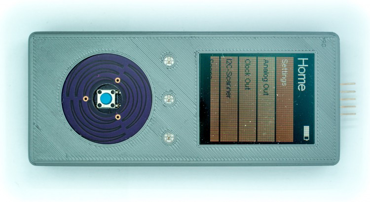
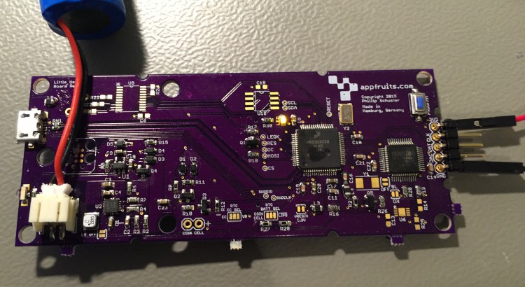
As you are reading this you might be interested in my custom built Teensy project named Little Helper. I made it Open Source under the MIT license including Schematics, Layout, BOM, 3D models of enclosing, and the complete Source Code. Have a look: Appfruits LittleHelper.

UPDATE (June 26, 2015):

Due to popular demand I have created a “reference board layout” and the schematics in EAGLE CAD (7.2) format. I created it by removing all components that were specific to my project. I just left in the Teensy part, the USB-port and a 3.3V regulator and rearranged the components so they fit in a small footprint. I have never produced the board but it should work (also it doesn’t do anything useful) as the components and layout have been working flawlessly in my own application.

This should speed up your development time for your own project. The board layout contains a switching regulator for the 3.3V which might be overkill if you are running your board of an USB-port as the provided regulator is mainly used with LIPO battery based projects and is hard to hand solder (I use a reflow oven which works quite well with QFNs). Use a simple LDO if you are just running your board with USB power. I have left the board layout for the switching regulator as it has been quite hard to get a good board layout with nearly no noise (switching regulators tend to be very noisy due to it’s nature) and should get you up and running quickly if you intent to do a LIPO-based project (of course you will need to add a LIPO charging circuit which can be found for example in Sparkfuns Power Cell product (see board and schematics for details).

All parts have an attribute named MPN for Manufacturer Part Number and MF for manufacturer. This way you can just use EAGLEs BOM-ULP script to export a BOM that you can directly upload to Mouser of DigiKey to get your parts.

Please note: Don’t order the MINI54TAN at DigiKey or Mouser. You will need to order the MINI54TAN at PJRC.com as this IC contains the core Teensy functionality!

You can find the EAGLE board layout and schematics in our Github repository: Custom Teensy 3.1 board layout and schematics. Please make sure to read this blog post before using parts or the whole “reference board” in your own project as there are quite a few things to consider which is largely documented and described below.


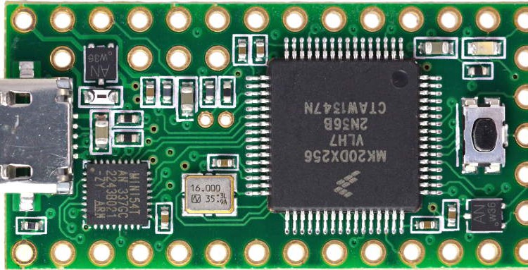
If you are reading my blog you might know that I really love Teensy. Teensy is an ARM powered very little Arduino compatible development board. It does one thing so damn good and I think that is very important for a development board and one of the keys to the success of Arduino: Easy programming. You do not need to connect wires and fancy boxes (JTAG programmers), just connect with USB and click on the program button.

But I am not a big fan of using development boards within final products. Although Teensy is really small it’s too high to pack two PCBs together. Using headers for easier soldering and it gets worse. If you really want to build small products you will often have to build your own PCB. Paul Stoffregen, the creator of Teensy enables these efforts by providing the bootloader MCU in his own store. They are very professionell. I had a few issues with german customs and they immediately sent out new ones and I received a refund for the first package that did not make it through.

Of course it’s not Pauls business model to help you out building your own Teensy, although he was very helpful in the forum. You will have to rely on the great Teensy community or blog posts like this one.

As I had a bit of trouble to get my custom Teensy board up and running I will try to give you some advice on how to build your own. (more…)

Read More

Do I need an Oscilloscope?

If you are interested in Electronics, you will likely ask yourself sooner or later if you need an oscilloscope and especially what to buy if you have decided to do so. As I have been in the same situation a few months ago I likely know what’s going on in your head. Give me a minute to save you a few more sleepless nights thinking about this topic.

You can find a lot of infos about scopes. You will find hundreds of hours of video reviews of scopes, just look at the amazing EEVBlog. But non if these videos really gave me an answer to my question: Do I actually need a scope and what can I do with it.

Did you love playing with your dads HIFI-system and turning the knobs? Well, I know a scope is kind of a sexy tool with it’s knobs for you… But do you really need one? (more…)

Read More

Compiling Qt 4.8.5 for Arietta G25

Arietta G25

On my way building an automated wireless home automation system I have been finally been drawn to Embedded Linux. It just makes sense. Driving Internet of Things devices based on Arduino or other directly programmed MCUs is not very efficient. You will have so much work with just building up a network stack for example based around a CC3000 (Available as a nice breakout board from Adafruit). And you will just redevelop what is available for linux for decades. But: Embedded Linux is a beast of a monster. It’s just a whole different universe.

There are so many devices to choose from, the most prominent example being the Raspberry Pi of course. But I wanted a solution that I can use for a final product. For my work I need a very small device and I don’t need all these connectors (Ethernet, HDMI, etc) so I have been searching the large catalog of SoMs (System on Module) and found “Arietta G25” by Acmesystems. I really love this little device and Acmesystems provides a lot of tutorials and help documents to get started quickly.

Find more infos about their great product line-up here: acmesystems.it.

After I had attached a 3.5 TFT (acmesystems has a well written tutorial on how to do that) I wanted to use it for a great User Interface. As you don’t want to build your own UI-System you will most likely find Qt. Qt is more than just a UI frameworks. It’s awesome as it features more or less the same as the whole Apple iOS system. It features it’s own (great) IDE, Interface-Builder for doing design work the WYSIWYG way and features an almost complete Framework with hundreds of C++ classes for all kinds of stuff. They even have a well written network stack helping a lot in doing IoT stuff.

But: Getting Qt to run on an embedded linux device is not that easy. It’s hard work. Requires hours of hours of your time building stuff. Of course there are systems like Yocto and Buildroot – I just got started with them and so far I don’t see it’s easier. As acme systems provides a few images to get started, I wanted Qt installed based on the acme systems solution.

(more…)

Read More

Teensy – Arduino on Steroids

I love the Arduino Eco-System. Although I do not really like the IDE, the whole system is awesome. And it allows to quickly prototype ideas. And, as everything is Open Hardware, it also allows you to build your own PCBs with the same components used by Arduino. I am not in the business for creating a large-scale electronics product. But it’s very important for me that I could.

While working on my DIY Home Automation System I noticed some limitations with the current Arduino Hardware Offers. I have created my own Atmel 328p based PCB for my sensor nodes. The Atmel 328p is the MCU that drives Arduino Uno, Nano, Micro Pro, Sparkfuns Redboard and various other Prototype Systems. This MCU is quite fast (up to 20 MHz), can be run on batteries for a long time (if you care about your current consumption) and is easy to use program with the Arduino IDE. But there are limitations. You only get about 2K SRAM and 32K of program memory. That is enough for devices that only connect to a few sensors, driving a few motors, etc. But it’s not enough for more complex projects.

My DIY Home Automation Network needs a hub, that acts as a bridge between the Internet and the sensor nodes. Sensor Nodes are using nRF24L01+ Radio Modules. The Hub also hosts such a radio module, but has to send the signals in to the cloud. Although I wanted to have nice devices in the end I tried an Arduino Yun as a hub. The hub does not have to be very pretty as it will be placed in a small room that is not exposed. A small enclosure will do it. Arduino Yun is a great device that hosts both an Arduino MCU and a full-fledged Linux on the same device, connected with a bridge. Using the bridge you can run shell commands from the Arduino MCU on the Linux side and receive the results. You do not have to build a whole HTTP-client, as Linux already has one. I have written a small tutorial about that: Running Node.js on Arduino Yun.

All of that worked fine – in the lab. Using the sensor networks in the wild (well, in my house), I found it very difficult to debug the system. In order to save power the nodes do not have any LEDs, Display, whatever. I added some LEDs to the Arduino Yun that showed it’s state and if sensor data came in. But all in all it did not really help. I found sensor data in the cloud, but not from all nodes. And I could not really see the routing in the nRF24L01+ network. Attaching displays to the sensor nodes has not been an option due to power restrictions. I had to add a display to the hub. That would give me the option of adding some sort of user interface to it. But Arduino Yun only has 2K SRAM, and adding a display and it’s quite large driver code I ended up with not enough SRAM left. I could optimize everything so it perhaps would fit, but I would not have any room to add a UI to the hub later on. I have been quite disappointed about this limitation. I think the Yun should have built with a beefier Arduino-MCU. It should be possible to drive a display trough the bridge from the Linux side, but that would be way to slow. Although I really liked the idea of the Yun, it did not fit my needs.

Teensy is here to help

Searching for an Arduino Compatible small device Google with tell you to have a closer look at: Teensy. Teensy is just an amazing piece of hardware, created by Paul J Stoffregen. Paul did an amazing job with Teensy, especially the latest version 3.1. Teensy ist very small. If you find an Arduino Nano or Micro Pro small, you will be amazed how small Teensy really is. And it’s very, very powerful. Teensy features an ARM Cortext MPU with 64 KB SRAM and 256 KB Program memory. That is a lot of space and enough to do a lot of cool stuff. What I really love about the Teensy is how bootloading it is solved. I had a few issues with programming Arduinos. Teensy features a tiny uploader software, that is either triggered by the Arduino IDE or by pressing the reset button on the device. And uploading new code always worked. I really love that. Just install the Teensy Hardware Plugin in your Arduino IDE 1.0.x (it does not support 1.5.x at the moment) and you are good to go.

(more…)

Read More

Custom LCD Controller for Printrbot Simple (Metal)

In order to print with the Printrbot Simple Metal you have to connect your computer with your printer via USB and make sure that the computer continuously sends data to the printer. If your computer crashes, your printer stops and your maybe long hour print is a piece of chunk. If your computer goes into stand by the result is the same. And there are various other reasons like energy consumption. The way to go is untethered printing.

The Printrbot Simple Metal is capable of that in two ways, both of them require a Mini-SD card inserted into the printer. The first way is to write the G-Codes generated by your Slicer, typically Repetier Host and Slicr to the SD-Card. Name it auto0.gcode, insert the card into the printer. Shut it down and on again. The printer should now start to print. But you will not know if it works for a couple of minutes as it’s first heating up. Nothing moves, etc. I tried that a couple of times and found the procedure to be very annoying.

The second method is using the Addon LCD Controller sold by Printrbot.

Getting your hands on a LCD Controller

Your Printrbot is already capable of displaying a nice LCD-Menu with all kinds of options and the option to browse the SD-card and run any print from it untethered from your PC. All that is needed is a Standard 20×4 LCD Display and a rotary encoder. A rotary encoder is a special kind of input sensor that sends signals when it is rotated.

Printrbot sells these LCDs for $65 in their store. But they still have that wood look. It does not match the Metals Design. And, as I am living in Germany you will have to wait a few days for it to arrive and you will likely have some issues regarding customs. I did not found a german distributor a few weeks ago so I wanted to built my own. A few days ago I have found 3ddinge.de selling the LCD Controller in Germany for €70. That’s a lot of money and by doing it yourself you will end up with 30-40 Euros for the LCD Controller.

(more…)

Read More