This blog post describes the details about the hardware, more specifically the PCB that I have developed for the display component of the new Printrbot Simple 2016. As we believe in Open Source we have published everything under the MIT license. Have a look at the code respository, too.
To give you some context why we have chosen these components please first read my Behind the Scenes report that describes the process of selecting the right components for our purpose.
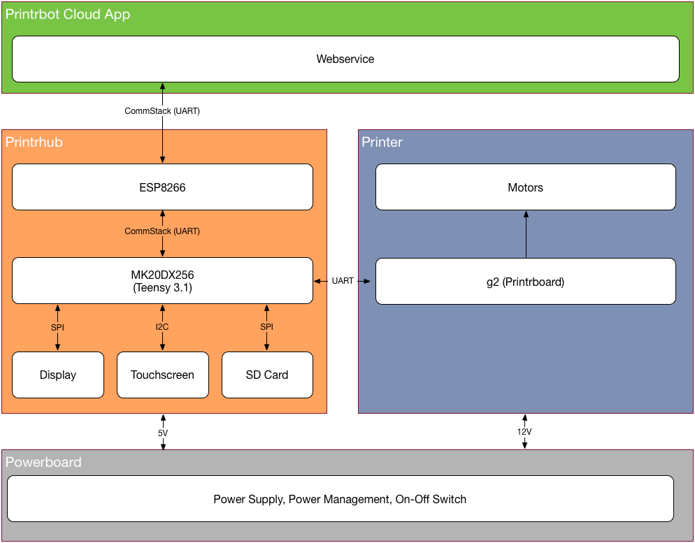
Block diagram
Let’s have a look at the Block Diagram of the Simple 2016 and how various components are connected. First we have a very clever power management that delivers enough current for all the motors and PCBs but also does that secure and with great efficiency. Next there is the Printrhub, which is the display component of the printer. The hub also controls the Printrboard and the ESP module to communicate with the Printrbot cloud that holds all the projects, materials and settings of the user. Last but not least there is the printer itself, powered by the g2 Printrboard with advanced motor handling features and advanced algorithms for great prints.
Schematics
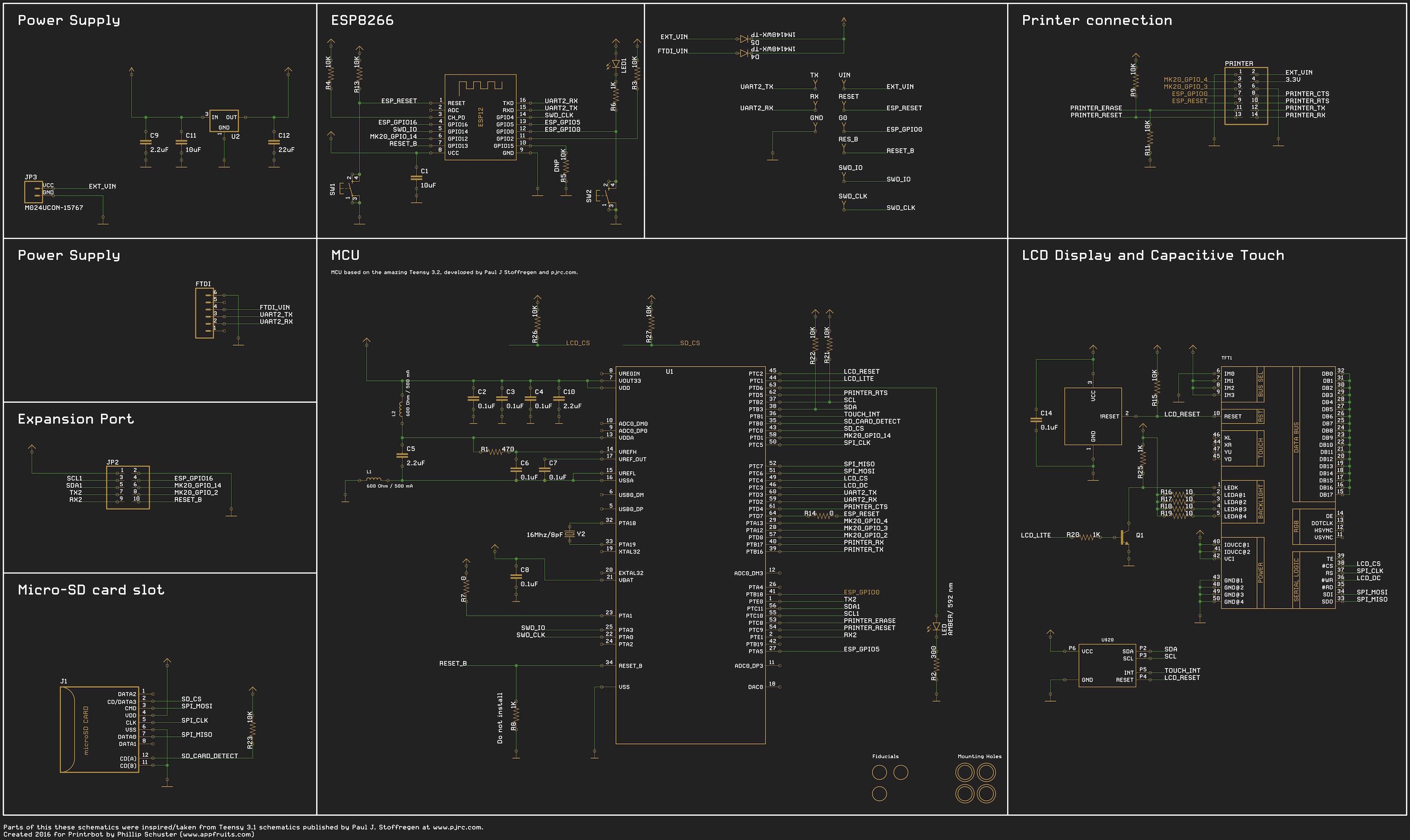
Let’s dive into the details of the schematics. It’s structured and separated by each component so you should quickly get an idea of how everything works together. If you ever worked with the Teensy you should see a lot of similarities between our design and the Teensy 3.2 design. However you may notice that the Teensy bootloader chip is missing. Instead these signals are routed to the ESP. As Teensy does not support over the air updates at the moment. We had to write our own bootloader for the MCU which is built in our ESP firmware. In our design, ESP flashes the Teensy MCU with firmware downloaded from the Printrbot cloud!
Our first revision of the Printrboard had the bootloader chip from PJRC installed, along with a USB connector. This allowed us to upload new code the same way as you do with your Teensy developer board. If you are interested in building your own device we suggest you have a look at Rev 0.1.
The printer is connected with a 14 pin ribbon cable. In fact. The “Printer Connection” goes to the power board that routes the signals to the printer board. This way we can enhance functionality in the future or even support different Printrboards.
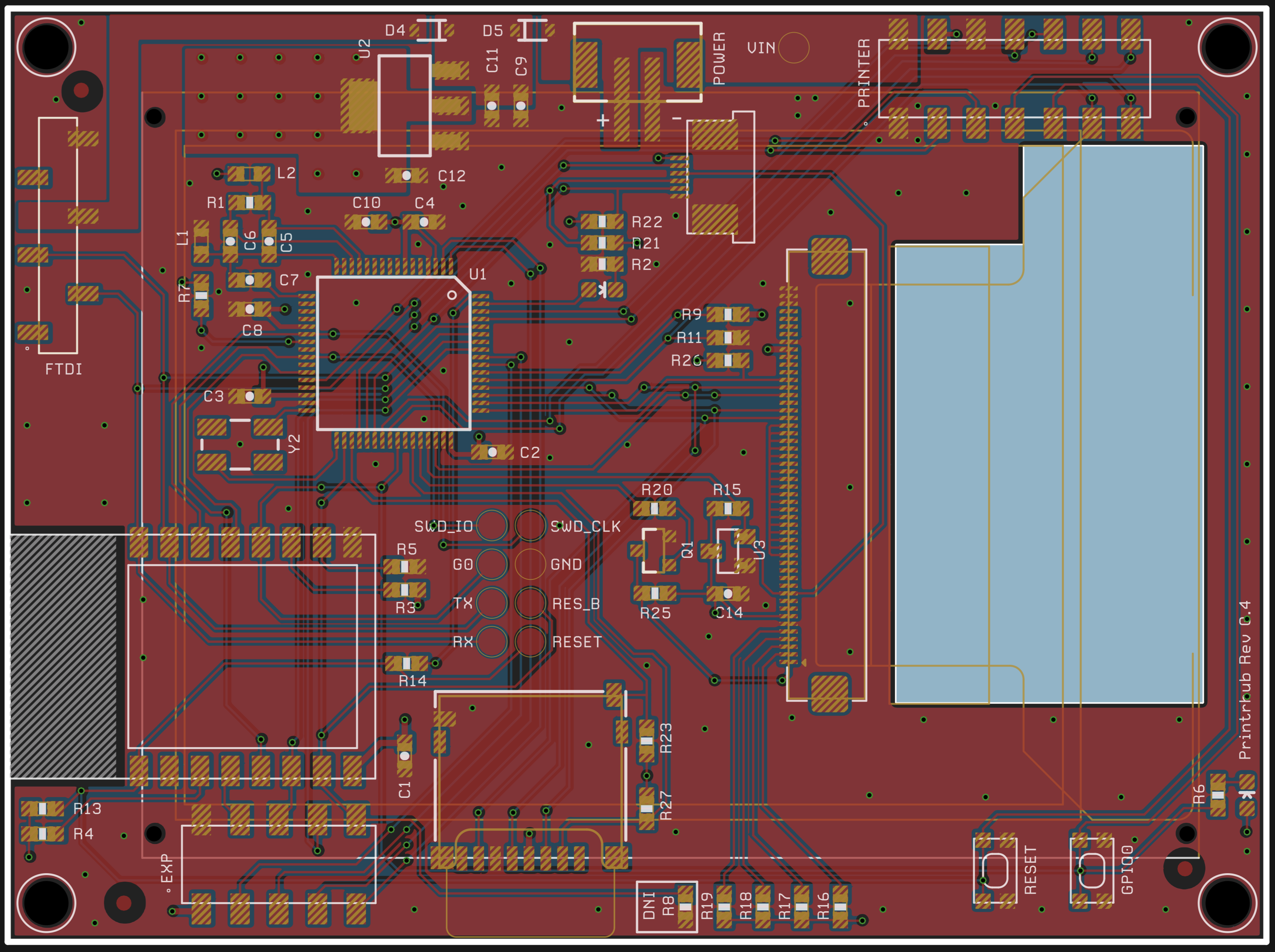
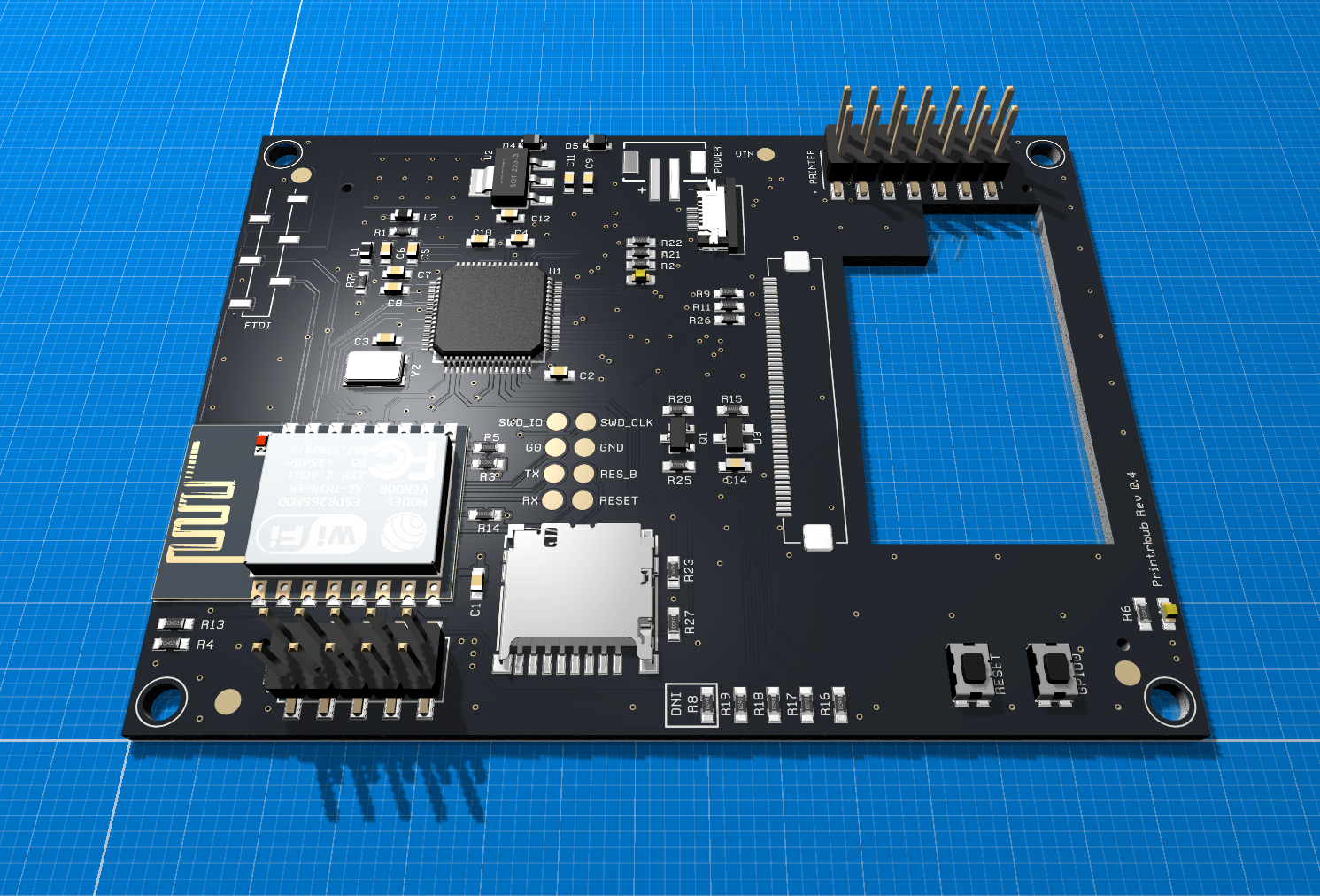
The layout
The board size has been constrained by the dimensions and the position in the printer. The display and other components had to be placed carefully so they fit into the printer enclosing and match up nicely. We have added large heat sinks to keep temperature low and added various expansion ports and test points we used during development. Test points are used during production to flash the initial firmware and to make sure everything works as expected. The blue area is a cut out of the PCB. We route the flex cable of the display through from the bottom side of the display to the connectors.
Important: If you want to flash your own ESP firmware you will need to pull RESET_B (labled RES_B) LOW. Solder some wire to the test point and connect that to GND before you start flashing ESP and remove it when the process has finished. Holding RESET_B to LOW shuts off MK20 which listens to the same Serial port as ESP is programmed. MK20 constantly interferes by sending reports and CommStack responses or requests while ESP is flashed and confuses the upload. You will receive strange errors and the upload will not succeed if you don’t shut off MK20. You will also need to keep GPIO0 button pressed, press and release the RESET button and then release GPIO0 to initate DFU mode of the ESP. The LED besides R6 will dim lightly if ESP is in this mode and accepts new firmware written.
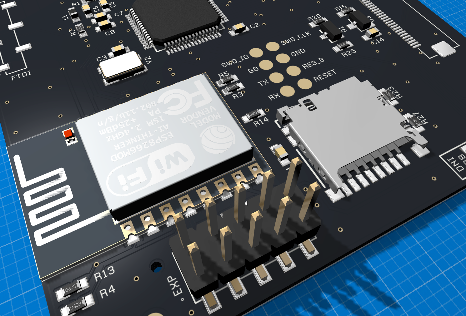
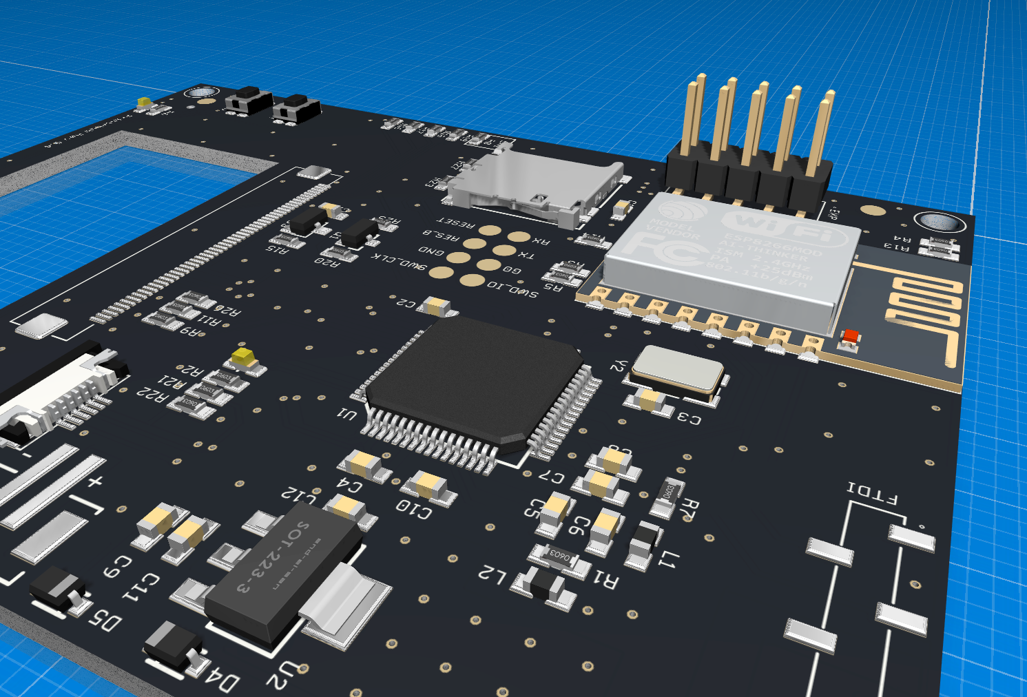
Some 3D views of the layout
As you might know I am developing a Mac software named Copper that helps in creating and finalizing PCBs and is also a great tool during software development as you can quickly look up pin numbers and connections. But it also permits to create nice 3D views of your design.
Hardware revisions
In total we had four hardware revisions. Release 0.3 had a dump mistake and didn’t work at all. We did not publish it as the only difference to Rev 0.4 has been a wrongly placed connector to the touch screen flex cable and we didn’t want to anyone produce PCBs of a design that does not work.
Revision 0.1
The first hardware revision had the PJRC Teensy bootloader chip and had a different size as the final dimensions haven’t been specified. Hacking software is very easy with it as you can just connect the display via USB and upload sketches using the Teensy loader. You can make the firmware compatible with Rev 0.1 by setting the correct define in the HAL.h file in both firmware repositories (esp and mk20 folder). There are some slight changes but overall this is a great revision to use the display as basis for your own design.
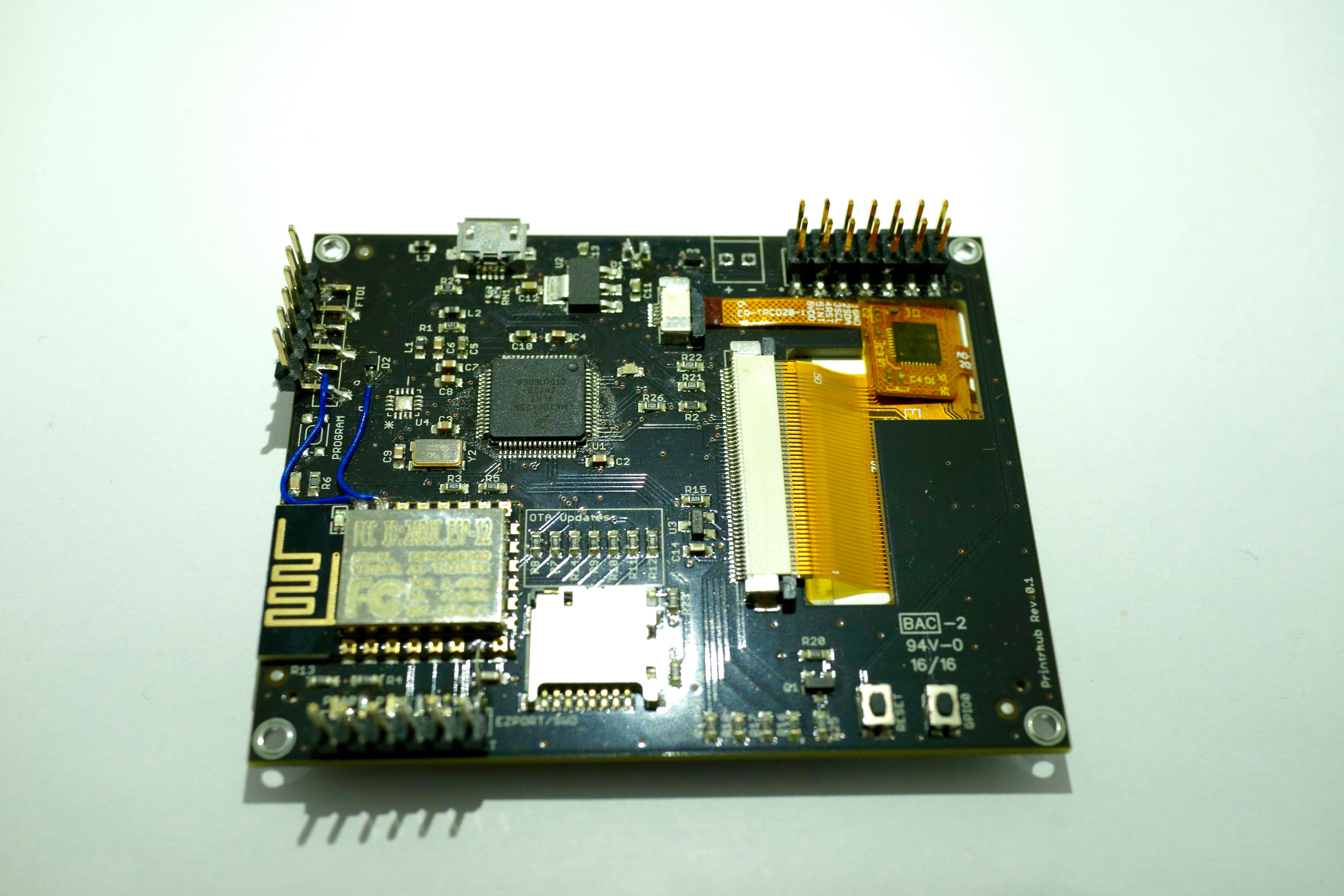
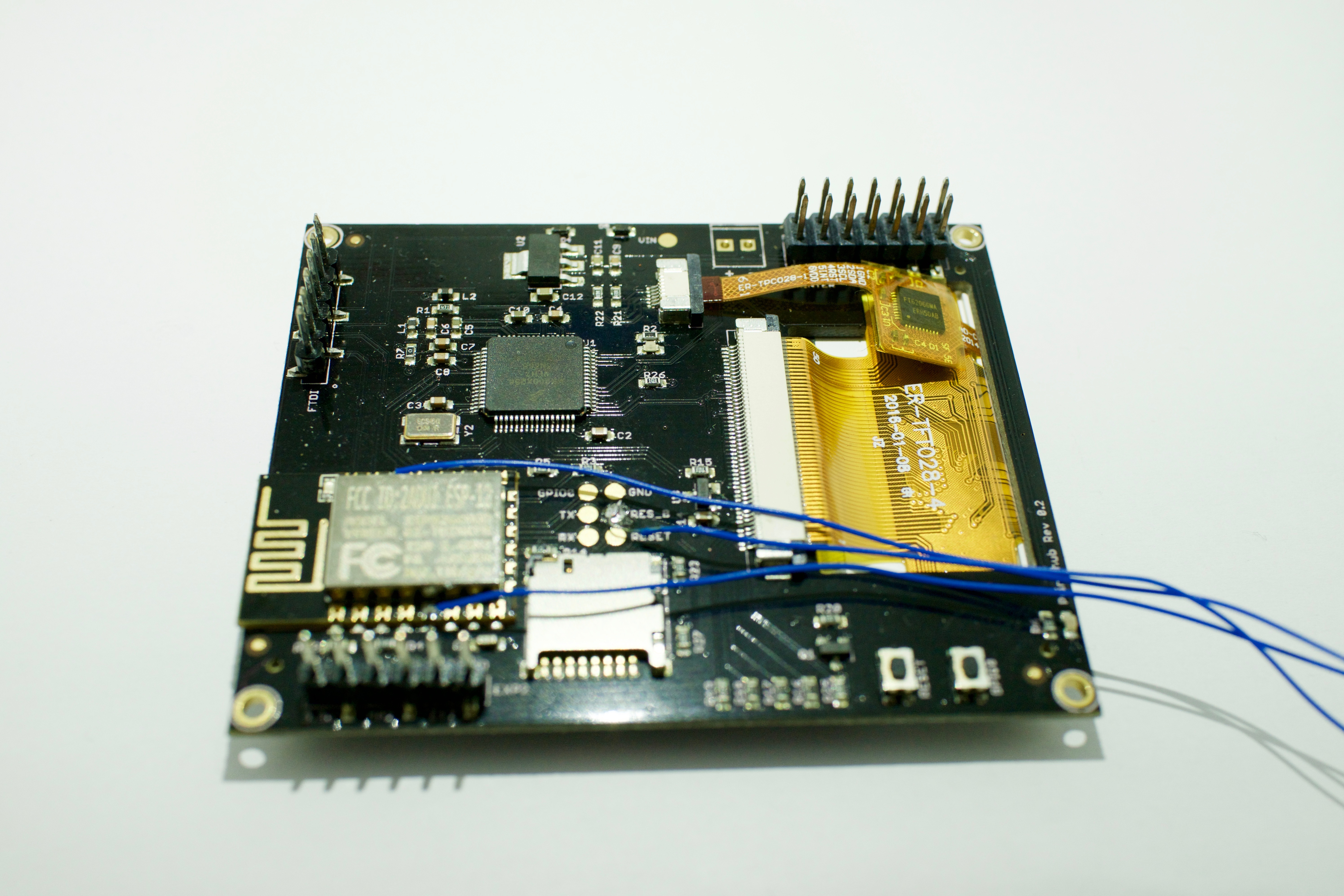
In the image the Teensy bootloader chip has been desoldered to test firmware updates in software using the ESP. There are also some “green” wires that were soldered on the board to fix some hardware issues.
Revision 0.2
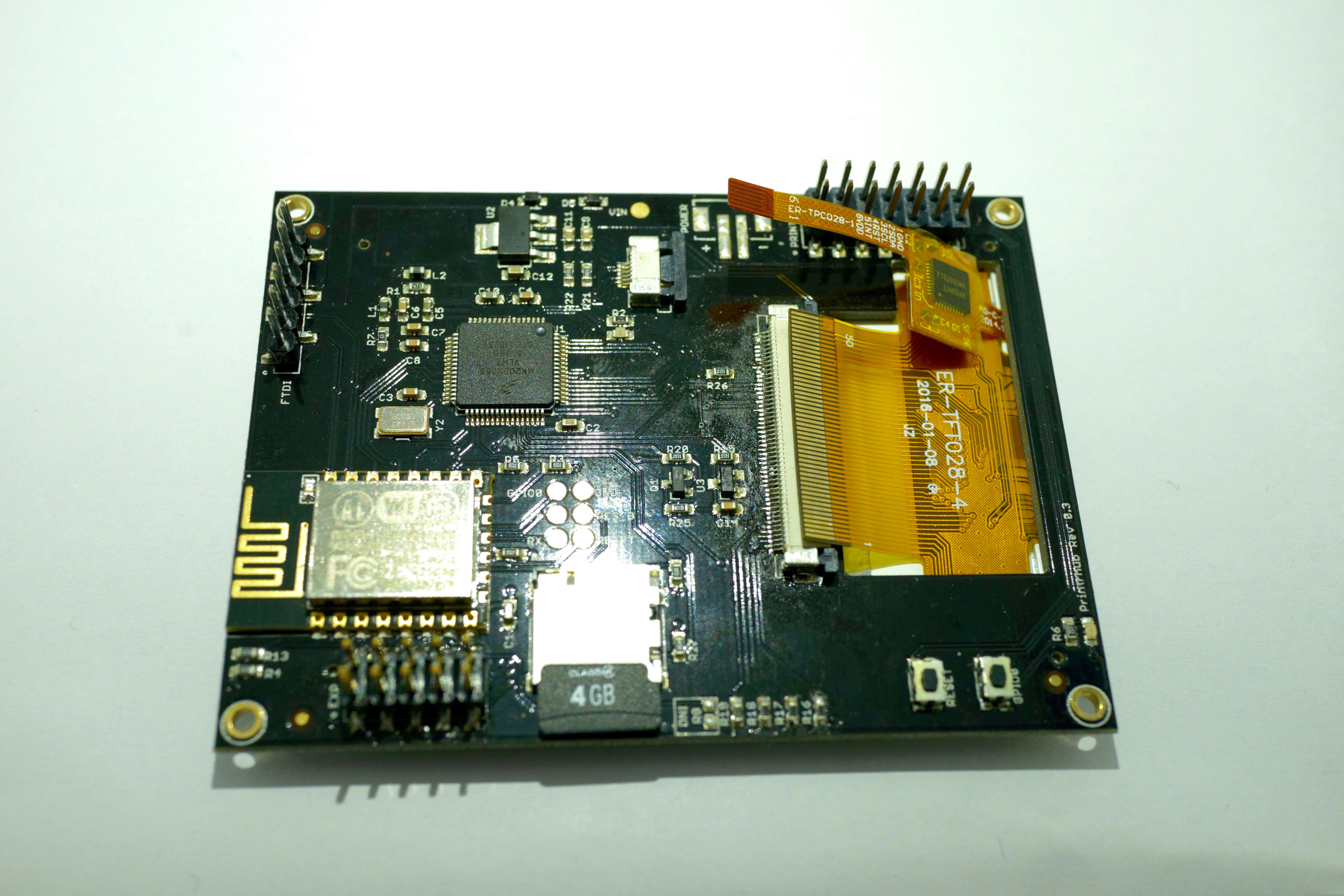
In Rev 0.2 I removed the bootloading chip for MK20 (Teensy bootloader), USB port and other circuits necessary for the bootloader. Instead I connected SWD signals of MK20 to ESP to allow ESP do the software update to MK20. I also added some test points. I did not expose SWD signals and we had to solder some wires to the SWD signals to connect them to our debug probe that allowed us the program the firmware of MK20 and debug it.
Revision 0.3
This should have been the final revision before release. But I failed! I had to move a lot of components around as the final device specification have been released. But I forgot to move the touch screen controller connector and it just did not fit (cable too short). So, Printrbot had to dump those PCBs :-(. I invested months in programming a software to prevent just that: Dump errors costing a lot of money and time. But even Copper didn’t help! But we all learned something and the next version of Copper will allow to set constraints to various parts and will check these constraints while you develop your design to prevent these kind of dump errors!
Revision 0.4
This is the same es Rev 0.3 but the touch screen controller has been moved to the correct position. I added a few signals to the expansion header and made some slight changes. This design worked great and is currently shipping with all Simple 2016 (without the resistor though).
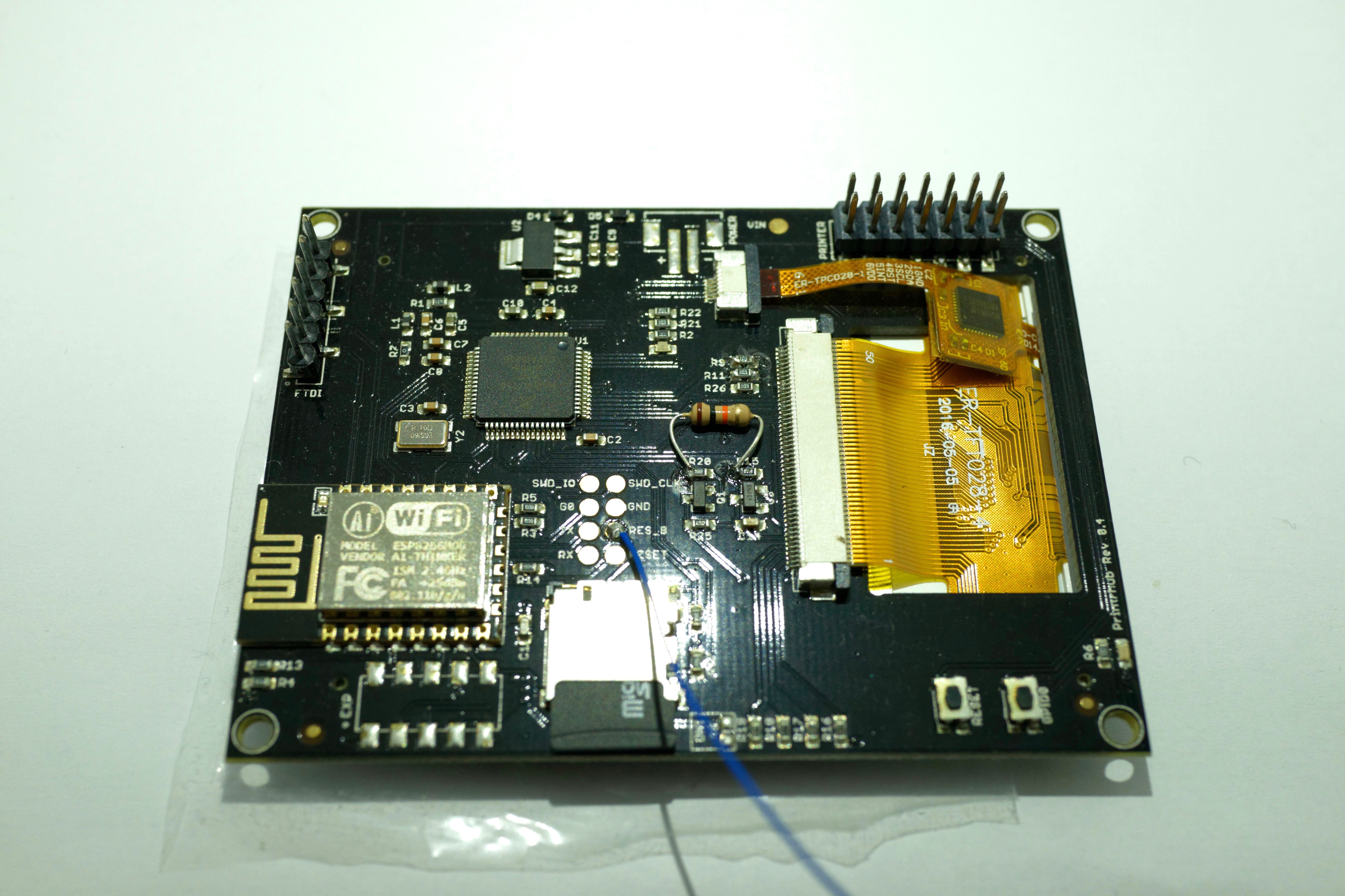
As you can see there is a small PTH-resistor soldered on the board. We do not rest on our successes, in fact we are working hard to further improve the software and hardware. This resistor has just been a test, but I wanted to show you that there is always a way to hack a board before ordering a new one or to try out new things.
Having the right tools is essential
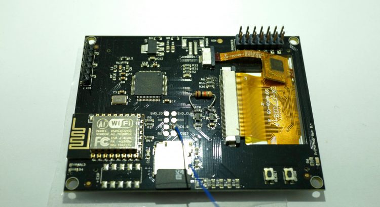
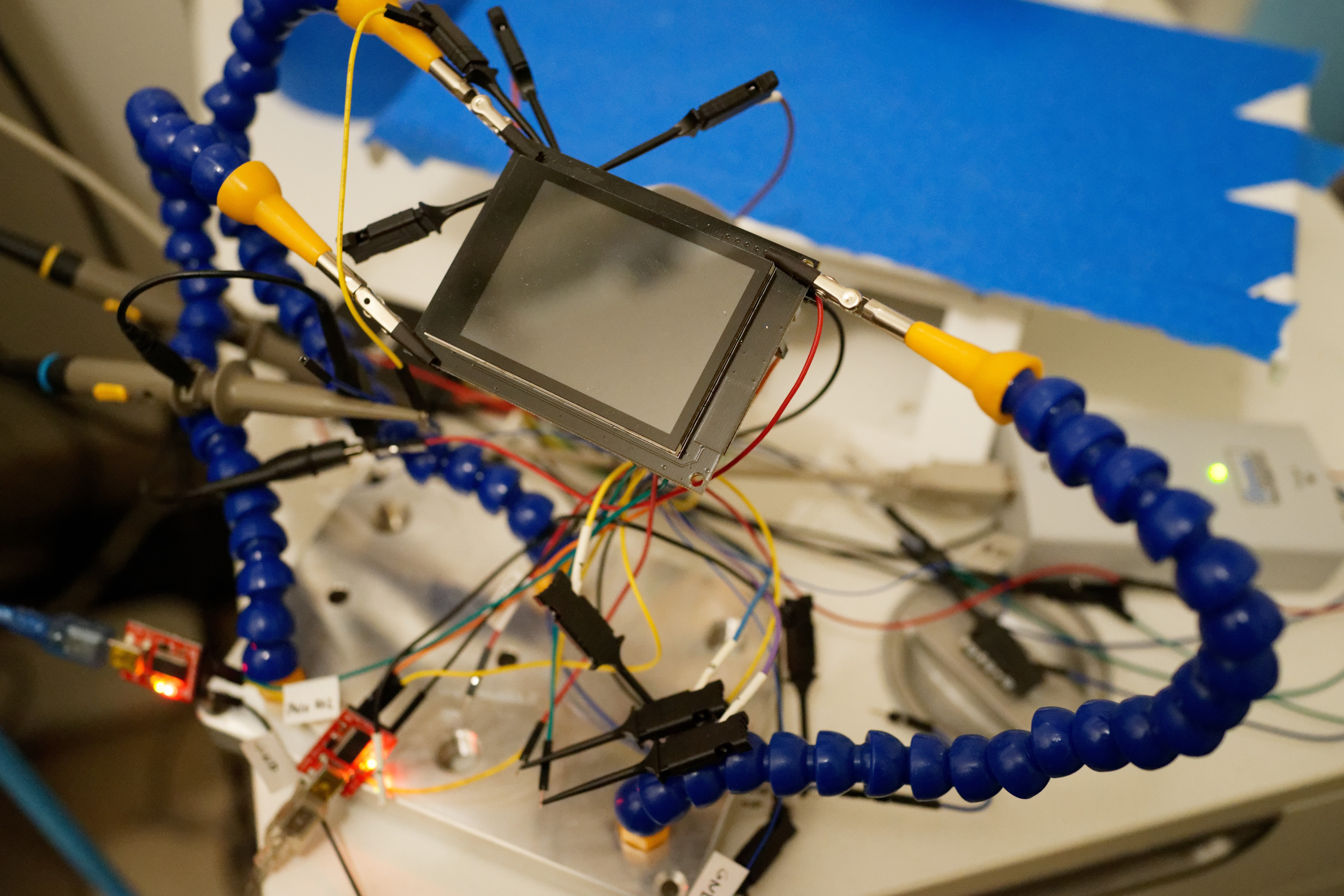
This is an image of my lab. It shows the display connected to the printer (visible in the background) and a mess of wires. These wires connect the display to various components and devices that allowed me to quickly check signals with the Logic Analyzer (Do I need one, too?) and the Segger J-LINK debug probe. While Mick loved to build Perfboards with fixed connections I went with the spaghetti solution, but taped small labels on them. This special setup made it easy to play with the display without ripping off wires all the time while moving it around. In total I have about 20 wires and two FTDI breakout boards connected.
Final thoughts
Besides the dump error in Rev 0.3 hardware development had been straight forward. As the design is based on Teensy 3.1 that I have been very familiar with I did not have much headache to built that. It’s also heavily influenced by my LittleHelper PCB that also featured display connection and various other components. You can find the EAGLE files in Printrbots Github repository.
Please let us know (@printrbot) if you are working with our design or hacking your Simple 2016. We are also interested to learn what you create!


Thank you for having posted this here. Otherwise I would have powered up my printer with the ribbon cable reversed. The pictures and instructions I would say are not ready for the real world for assembling the 2016 Simple printer yet.
Thank you for having posted this here. Otherwise I would have powered up my printer with the ribbon cable reversed. The pictures and instructions on the Printrbot.com website for assembling the 2016 Simple printer I would say are not ready for the real world yet. It’s a challange! I’m still searching the web for pictures of how to route the cables within the printer to the extruder. I enjoy a challange. This is my second Printrbot!
Hi David,
thanks for commenting about this. I have forwared your task to Printrbot. They will add instructions for the ribbon cables to their guide. They will constantly update to fight any issues you or other users might have. So please let them know where you got stuck, either by posting it here, or even better directly by contacting Printrbot-Support.
Cheers,
Phillip
Thank you for this nice post. I also ordered a DIY kit of the Printer. I had the same problem as David. It was very hard to assemble the Printer, before printrbot updated their manuals. Unfortunately there is an issue with the display board. I already had a chat with the printrbot support over two weeks without any outcome regarding to the problem.
When I started the printer first everything switched on and the boot-up was processing. After about 5 seconds it switched off without any reason. This happened two times. After then it stopped doing anything. I checked the display board and recognized the two LEDs at the back. When I power up the printer the LEDs are flashing on time and nothing more. Do you have an idea what happened to the display board. Do you think there is a way to fix this or do I have to replace the board?
Thank you
Best regards
Sydney
Hi,
I am sorry that you have issues with your printer. When the LED (should be orange) near the display connector (in the middle of the board) is flashing it indicates that the firmware of the MK20 is loaded as this pulse is activated once everything is setup. This is a good sign. However, hard to tell from the distance what is wrong. But there are a few things you could do. Try to make a photo of the display. It’s possible that the display is working fine, but background lights don’t. Then sometimes when making a photo you can see the display actually shows something. Also make sure the display flex cable is correctly installed in the connector. Have a look at the photos of the article to see how they are supposed to be installed.
If you have a FTDI cable lying around you could connect it to the expansion port (bottom left footprint below the ESP module) on signal TX2 and RX2. RX2 and TX2 are the rightmost bottom pins of the expansion header when the board is orientated like in the photos. Connect RX2 to the TX pin of the FTDI cable and TX2 to the RX pin of the FTDI cable or breakout board. Also connect GND to any GND pin of the board (there are quite a few exposed in the headers). You should then be able to open a serial monitor and get some log output of MK20 to see if it does something.
Of course this only makes sense if you are really interested in hacking it. Then I am here to help. If you just want to print, I suggest you get a new LCD and powerboard PCB as there could be an issue with one of them. Please make sure you send the boards to printrbot once you got the replacement boards so we can investigate the issue. I’ll have a chat with printrbot regarding your issue. You should here something from me or printrbot a.s.a.p.
Hi Phillip
Thanks for your fast replay.
Yes I understand that it is hard to say whats wrong from the distance.
Actual I only see two LEDs switching on and off again and nothing more. One LED is located at the esp mcu (blue) and the other is at the right lower side on the board (yellow – green). If I press the button near the LED it switches on and on again when I release.
Regarding to you question if I would like to hack the board. The answer is yes and no. I’m located in Germany, so its is very hard to receive something from the US. Anytime I get a package I have to go to the customs and pay tax. So I try to fix the problem by my own, first. I bought the printer with the plan to hack the board and change the firmware. But before, I need a working printer 😛
I’m used to deal with embedded stuff since years. I also have a Segger J-Link and of course a FTDI cable lying around ;). So I only need some advice how to determine the problem. I will try to connect with the FTDI cable, but I don’t know if I have a smd pin header for the expansion header. It is not assembled on my board. Or should I try to flash the Firmware of the MK20 over SWD? Maybe there is something wrong?
Yesterday I managed to connect to the Printrboard G2 with a USB cable. So it was possible to move the axis, heat up the extruder and change the color of the light. I think the Printrboard is working. But unfortunately printrbot only provides the cnc gcode sender for mac. And I didn’t get the cnc-client (printrbot repo) to work for Linux. So I was not able to start a print.
Best regards
Sydney
Sidney,
I was going to say I am in the same boat. After powering up for less than 5 seconds this happen 3 times and then it has done nothing since. Looks like you’ve made some progress.
Me: No blue LED on the printer board unless I move one of the stepper motors. No LCD. I’m under the impression the LCD must use 12 volts. There’s no 12 volts on the output connector on the power board when there is 12 volts on both sides of the fuse. I was able to create a user account on printrbot.cloud. I had to remove the microSD card to copy the S/N though. One of the things Printrbot support suggested I do was the #firmware but I can’t do that as I have not been able to add a printer to the Printrbot.cloud. To add a printer you have to know the IP address. Printrbot support has averaged 5 days between responses. I’m being to think I must have the patience of Job.
David
Important: The display needs 5V. Not 12V. As far as I remember we had some issues in early board revisions with power supply coming from 12V. You should connect the LCD display to the power board with a ribbon cable. The power board supplies 5V to the display.
When powering up, the LED on the ESP-module should flash. And the LED in the middle of the board (near the display connector) should pulse for 0.5 seconds during start (0.5s on, then permanent off).
If none of the LEDs is working, then the board is either damaged (LDO or ESP module, both or anything else) or it does not get (enough) power.
Phillip,
The grey cells are rusty. Picture Santa with the white beard and wire rim glasses. Even wearing the red hat with white fur rim as I’m writing this. 😉
I like your Bio. I bought my first home computer in 1981 with the Apple 2+. I think it was Fortran I started with in high school in 1969. Electronic technician in the Navy. Work for a couple telecom test equipment manufacturers as a test engineer before finally getting my BS in Computer Engineering Technology. Now I buy research…
I’m looking at the block diagram now. The LCD board is connected to the power board with the ribbon cable. I don’t have 12V going to the printer board. I’ve measured 0v on the 6-pin molex connector. I know the Webservice works as I’ve been able to login to it. Most likely something is damaged. I don’t want to replace a board without knowing what damaged it. And then put a procedure in place to prevent it from happening again.
David
Hi Philip,
I’m trying to locate the pin which supplies +5v to the LCD. Can you describe which one it is?
Hello, I’m trying to reconstruct a printrhub from a blank (I think) board I recently got from Brook. I have downloaded the repository and see the .bin files for the ESP and the MK20. I have gotten the Espressif Systems flash tool working and connected to the ESP8266… Now my question is: At what address do I load the esp.bin file? Alternatively, what tool did you use to flash the ESP8266? Regards, Jon.
Any ideas where I can get a powerboard for the simple Pro?